Several factors can influence boost pressure and affect turbocharger efficiency.
Boost Pressure: Several factors can influence boost pressure and affect turbocharger efficiency.
The key factors are:
Ambient Air Temperature and Pressure
As the air temperature rises, the ability of the turbocharger to compress the warmer air decreases. This phenomenon is directly due to the decrease in air density and the physical limitation of the turbocharger.
Even when the air temperature is low, the air density (barometric pressure or boost pressure) may be low. Under these conditions, lower than expected boost pressure may be experienced. The diameter of the exhaust system will vary the pressure differential across the turbine. A larger exhaust allows the turbocharger to rotate faster, which results in higher boost pressure.
Any increase in boost pressure would require “re-mapping” of the ECM programs to accommodate different air flow rates and resultant ignition change requirements. Over-revving of the turbine – trying to supply enough boost – can lead to turbocharger failure, particularly in conjunction with the increase in the pressure differential across the turbine.
Turbochargers are fairly simple in concept, but adapting the system to modern vehicles can be quite complex. This primer for those new to servicing turbos and review for veterans lays out the function and operation of turbocharging in Subaru vehicles.
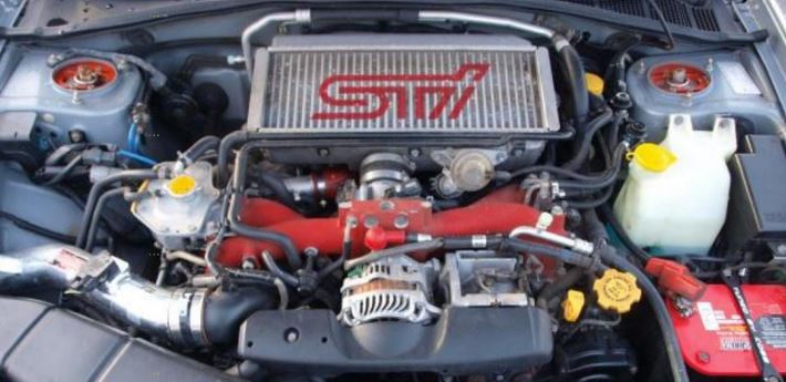
Subaru Turbocharger: Starting with 2004 models, the WRX STi incorporates a water spray system to help cool the intercooler, thereby further cooling the intake air.
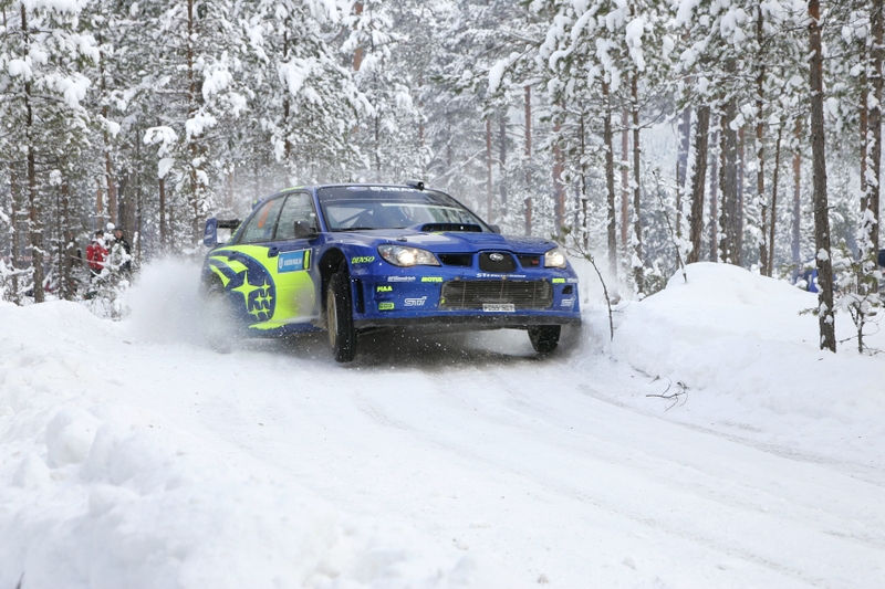
The return of turbocharging in the 2002 Impreza WRX marked an absence of nearly a decade for Subaru vehicles. While the new generation has been around for half a decade, not everyone understands the function and operation of Subaru turbocharging systems.
Naturally, everyone knows these blowers are designed to get the maximum power out of engines by packing more air and fuel into the cylinders to get the biggest bang possible. Just how that is accomplished, however, may be a bit of a mystery to you. Here’s a primer on turbocharging and how it applies to Subaru vehicles.
Subaru Turbocharger Explained:
A Brief History of Turbochargers
Turbochargers were originally invented to increase the volume of air pushed into the cylinders of internal combustion engines, and, along with increased fuel, raise the level of energy produced by the combustion process
Historical references indicate that Swiss engineer Alfred J. Buchi adapted the turbines from steam engines to diesel engines as a method to improve air induction, and, therefore, smoother operation in internal combustion engines. In 1905, Buchi’s idea of powering the forced air induction by exhaust flow was granted a patent. Good idea or not, the fairly crude engines of the day could not sustain even or adequate boost pressures. Buchi worked another ten years before he could produce a working model of a turbocharged diesel engine. By that time, other companies had also produced turbocharging systems
The massive building boom of internal combustion engines to supply ships, trucks and airplanes for World War I saw technologies take a giant leap forward. The first turbocharged diesel engines for ships and locomotives appeared around 1920. Shortly thereafter, European car manufacturers began incorporating them into factory race cars and a few sporty luxury models.
The next milestone for turbocharging came with the military build-up for World War II, when turbo systems were fitted to fighter planes and bombers to allow them to fly at higher altitudes where the thinner air could be compacted into the engines to provide sufficient combustion. However, direct-driven superchargers quickly proved more reliable, efficient and more easily controlled, leaving turbochargers by the wayside.
It wasn’t until the mid-1950s when turbochargers started appearing on diesel trucks that modern turbos began to make a dent in the automotive market. Today, the vast majority of truck engines are turbodiesels.
When turbocharged vehicles began to dominate the international racing scene in the 1960s, car manufacturers began to use them in sporty models to appeal to performance-oriented drivers. By the 1980s, turbochargers for cars were a bona fide success, particularly in Subaru vehicles, due to improved metallurgy, intercooling and efficient boost controls.
The main components of a Subaru turbocharger system are a water-cooled turbocharger, an air-cooled intercooler, a wastegate control solenoid valve, sensors and a controller. Let’s review the individual components and the role they play in the system.
Emission testing of a Full-Time 4WD or all-wheel-drive vehicle must never be performed on a single two-wheel dynamometer, nor should a state I/M program inspector or its contractors install the FWD fuse in the engine compartment. Attempting to do so will result in uncontrolled vehicle movement and may cause an accident or injuries to persons nearby.
State Emission Testing Subaru: Emission testing of a Full-Time 4WD or all-wheel-drive vehicle must never be performed on a single two-wheel dynamometer.
Resultant vehicle damage due to improper testing is not covered under the SUBARU Limited Warranty and is the responsibility of the state I/M Program or its contractors or licensees.
The 1990 Clean Air Act Amendments require the Environmental Protection Agency (EPA) to implement programs to reduce air pollution from motor vehicles. Certain states are required to adopt either a “basic” or “enhanced” vehicle Inspection/Maintenance (l/M) Program, depending on the severity of their air pollution problem.
The ‘enhanced’ I/M emission testing simulates actual driving conditions on a dynamometer and permits more accurate measurement of tailpipe emissions than the ‘basic’ I/M test, which measures emissions only during engine operating conditions at idle and 2500 RPM. The ‘enhanced’ l/M test also includes a pressure check to identify evaporative emissions leaks in the fuel system.
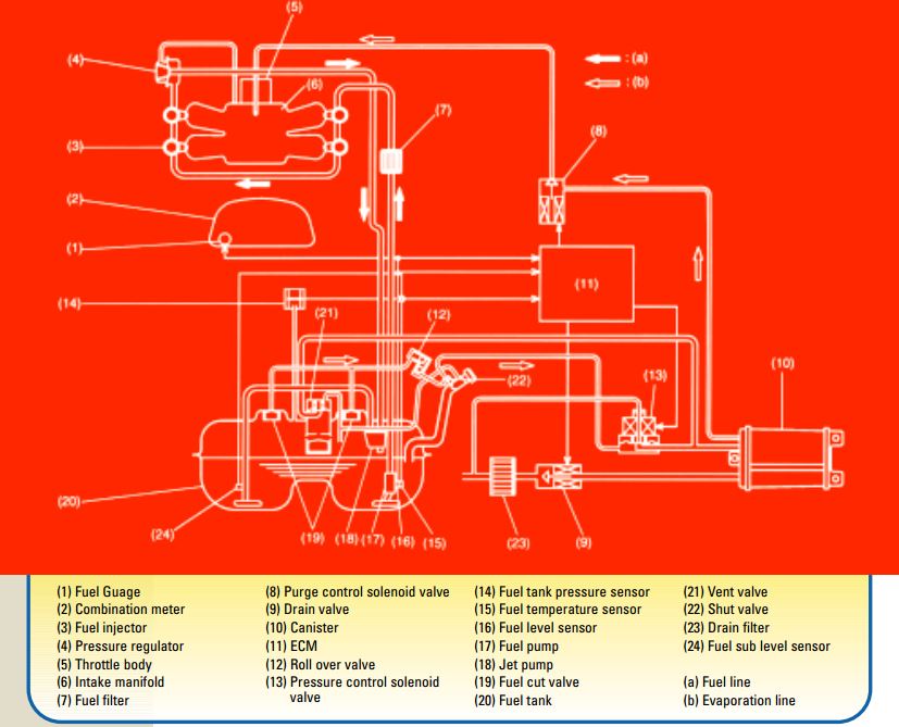
A major component of the Subaru OBD-II system is the system’s ability to monitor the evaporative emissions system. Today’s vehicles are producing very low emissions from the tailpipe, so it has become increasingly important to monitor and contain emissions from other vehicle sources.
Evaporative Emissions Testing Subaru: A major component of the Subaru OBD-II system is the system’s ability to monitor the evaporative emissions system.
A potentially large source of emissions is the vehicle’s fuel system. If not properly contained, vapors escaping from the fuel tank could produce a larger quantity of harmful emissions while the vehicle was standing still than what would be emitted via the tailpipe when the engine was running and the vehicle was driving down the road.
The Subaru OBD-II system monitors the evaporative emissions system by drawing the system to a negative pressure. If the system holds vacuum, it passes the test. If the system fails to hold vacuum for the prescribed period, it fails and a diagnostic trouble code (DTC) P04440 is stored in the ECM memory. The malfunction indicator light (MIL) also comes on in the dash to alert the driver to the problem.
The charts that follow were collected through the data link connector using the New Select Monitor (NSM), during the diagnosis of a DTC P0440 on a 1997 Subaru Legacy 2.5 liter. We’ll begin with a description of system operation under normal operating conditions.
Subaru vehicles are more reliable than ever before. To assure their continued reliability, a schedule of inspection and maintenance (I & M) services is prescribed by Subaru of America for every Subaru vehicle sold. A copy of this schedule can be found in the Warranty and Maintenance Booklet located in the vehicle glove compartment.
Maintenance Inspections for Subaru: Subaru vehicles are more reliable than ever before. To assure their continued reliability, a schedule of inspection and maintenance (I & M) services is prescribed by Subaru of America for every Subaru vehicle sold.
Subaru vehicle maintenance inspections services are divided into recommended intervals beginning with three months or 3000 miles (whichever comes first). Each additional level in the maintenance schedule (7,500/15,000/ 30,000 miles) adds more maintenance and inspection steps to the process. The 15,000 (15 month) and 30,000 mile (30 month) services are ‘major’ services, and include the most comprehensive range of component checks, part replacements and adjustments.
If you are already familiar with Subaru vehicles, you may have developed a routine when performing a vehicle safety maintenance inspections. Following a set routine allows you to start at one end of the vehicle and end up at the other end, having performed all of the necessary safety inspection steps along the way.
Repetition of the safety inspection may also allow you to commit the steps to memory, but a checklist can be a helpful addition that leaves nothing to chance (or memory). Checking items off the checklist provides a written record that can be shared with the customer and retained for your service records as well.
Recommended steps in a Subaru Safety Maintenance Inspections are also spelled out in the owner’s Warranty and Maintenance Booklet. Some of the steps overlap services performed during the scheduled maintenance program. It could be argued that any scheduled maintenance should always include a Safety Inspection. Most of the Safety Maintenance Inspection steps are based on common sense, but it’s surprising how frequently these simple suggestions are ignored.
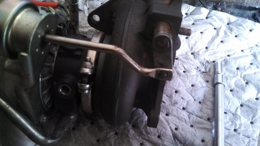
Boost creep is a situation where your wastegate port is not large enough to allow the exhaust gas to bypass the turbo. What happens is the exhaust gas will choke the wastegate port preventing further gas flow through the port. Then, the exhaust gas has to take the path of least resistance which is through the turbine of the turbo. This will spool the turbo ‘uncontrolled’ beyond your normal controlled max boost level.
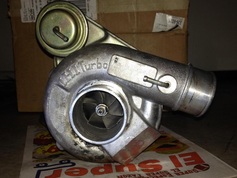
Wastegate and Boost Creep FAQ: A stock Subaru turbo.
The turbo will be spooling past wastegate spring rate pressure even though the wastegate is fully open thus it is uncontrolled. The best way to check for boost creep is to connect the turbo outlet port directly to the wastegate actuator port and go for a drive. In 4th gear you should normally get a stable boost level of about 0.5 BAR, if you have boost creep the boost will hit 0.5 BAR and will continue to rise with rpm until you either back off or hit overboost fuel cut.
Boost creep should only be present on a turbo that has very little restriction. For example a fully de-catted and high flow induction. It’s been found that the fast spooling IHI VF35 is very prone to boost creep. The cure is to remove the turbo and enlarge the wastegate port. Then, fit a stronger actuator 0.75 BAR the reason for this is because you have made the wastegate port larger. The effective size of the wastegate plate acting against the exhaust gas flow is larger which allows the exhaust gas excert more force on the wastegate plate.
This in effect weakens the effectiveness of the actuator. Before the increase in size of your wastegate port the actuator would open at 0.5 BAR, after the increase the actuator would open earlier at 0.3–0.4 BAR. After these changes are made to the turbo either a boost controller or a remap (to adjust solenoid duty cycle) should be sought to control the boost to a safe level.
This is a step by step guide on removing and re-installing a oil pan on your Subaru Impreza STi or WRX. This guide is also useful for installing a STi spec oil pan onto your WRX. This guide also is helpful if you are removing your stock oil pickup tube that is known to crack on the STi. I suggest purchasing a Killer B Motorsport Pickup Tube along with a brand new STi oil pan. Both can be purchased from down below from Amazon.
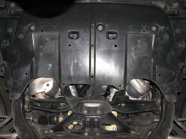
1) Remove the plastic under tray from your engine. This is secured using a few bolts and plastic push clips.
2) Remove the plastic under trays from either side of the car, the long ones.
Oil pan removal and install: Remove plastic to gain access to the bottom of the engine.
3) Remove the jacking plate. This is held on by 2 12mm bolts with nuts in the front, 2 12mm bolts in the rear and 4 14mm nuts on the sides.
4) Remove your subframe. This is secured by a few 19mm bolts, 2 12mm bolts in front and 4 14mm bolts. I highly recommend soaking these all in your PB blaster and waiting 5 minutes. Check out some of my other posts for instuctions.
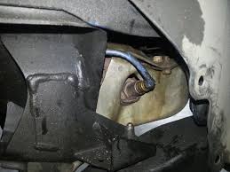
5) Remove the front oxygen sensor. The correct way is to unplug the clip, unhook it from the metal mount and then pull the wire through the fender-well so that the wire isn’t being stretched and twisted as you unscrew it.
Bone stock the WRX is one of the best performing entry level sports cars you can find, but there’s always room for improvement. Replacing the stock 2.25″ turboback exhaust and it’s 2 catalytic converters with a 3″ turboback exhaust, featuring one high flow cat, should allow the turbo to spool up easier and quicker for more low end grunt.
1.) Remove the heatshield. You’ll be amazed at the amount of bolts used to hold on this simple piece of metal. There are 5 on the left side (viewing from the front of the car), one on the back, and two on the right side. After you have all the bolts removed you’re going to need some keen geometry skills to get the heat shield out of the engine bay but once you do, the downpipe to turbo connection is easily available. Once the downpipe is exposed look for the bottom heatshield. It connects to the downpipe by one bolt.
2.) Loosen the downpipe. There are only 5 bolts holding the downpipe to the turbo. They are surprisingly easy to get to. Now would also be a good time to remove the O2 sensor from the Downpipe.
3.) Disconnect the remaining hangers. It’s a good idea to use photos of the exhaust out of the car in order to point out where the hangers are in relation to the whole system. Install the new downpipe by lining up the turbo/downpipe bolts then securing the hangers. There are 2 hangers for the downpipe shown here. The front one bolts into the transmission. The second rests on a J bracket and is screwed in.
We use cookies on our website to give you the most relevant experience by remembering your preferences and repeat visits. By clicking “Accept”, you consent to the use of ALL the cookies.
This website uses cookies to improve your experience while you navigate through the website. Out of these, the cookies that are categorized as necessary are stored on your browser as they are essential for the working of basic functionalities of the website. We also use third-party cookies that help us analyze and understand how you use this website. These cookies will be stored in your browser only with your consent. You also have the option to opt-out of these cookies. But opting out of some of these cookies may affect your browsing experience.
Necessary cookies are absolutely essential for the website to function properly. These cookies ensure basic functionalities and security features of the website, anonymously.
Cookie
Duration
Description
cookielawinfo-checkbox-analytics
11 months
This cookie is set by GDPR Cookie Consent plugin. The cookie is used to store the user consent for the cookies in the category "Analytics".
cookielawinfo-checkbox-functional
11 months
The cookie is set by GDPR cookie consent to record the user consent for the cookies in the category "Functional".
cookielawinfo-checkbox-necessary
11 months
This cookie is set by GDPR Cookie Consent plugin. The cookies is used to store the user consent for the cookies in the category "Necessary".
cookielawinfo-checkbox-others
11 months
This cookie is set by GDPR Cookie Consent plugin. The cookie is used to store the user consent for the cookies in the category "Other.
cookielawinfo-checkbox-performance
11 months
This cookie is set by GDPR Cookie Consent plugin. The cookie is used to store the user consent for the cookies in the category "Performance".
viewed_cookie_policy
11 months
The cookie is set by the GDPR Cookie Consent plugin and is used to store whether or not user has consented to the use of cookies. It does not store any personal data.
Functional cookies help to perform certain functionalities like sharing the content of the website on social media platforms, collect feedbacks, and other third-party features.
Performance cookies are used to understand and analyze the key performance indexes of the website which helps in delivering a better user experience for the visitors.
Analytical cookies are used to understand how visitors interact with the website. These cookies help provide information on metrics the number of visitors, bounce rate, traffic source, etc.
Advertisement cookies are used to provide visitors with relevant ads and marketing campaigns. These cookies track visitors across websites and collect information to provide customized ads.