The turbocharger terms and definitions used to describe turbocharger operation can be confusing.
Turbocharger Terms and Definitions: The turbocharger terms and definitions used to describe turbocharger operation can be confusing.
Here are some definitions for common turbocharging terms:
■ Boost Threshold
Boost threshold is the optimum engine speed to produce exhaust gas flow to create positive manifold pressure (boost).
■ Turbo Lag
Turbo lag is the time delay between the point when the throttle is opened and the turbocharger boost reaches operational speed when the engine is running at boost threshold.
Engine tuning status; the condition of the rotating components; operational condition of the control sensors and components; the presence of any air leaks in the turbocharger system; the control settings; and even the weather.
■ Boost Leak
When air (boost) is leaking within the turbo system or intake, it is referred to as “boost leak.” This may be caused by loose assembly of the components, a bad seal or a cracked component. Under such a condition, the turbocharger may not create enough boost pressure, or reach adequate levels.
■ Boost Spike
A boost spike is an erratic increase in boost pressure, mainly experienced when the vehicle is accelerating through the lower gears and the controller can’t adjust to the changes in engine speeds as quickly as would be ideal.
Several factors can influence boost pressure and affect turbocharger efficiency.
Boost Pressure: Several factors can influence boost pressure and affect turbocharger efficiency.
The key factors are:
Ambient Air Temperature and Pressure
As the air temperature rises, the ability of the turbocharger to compress the warmer air decreases. This phenomenon is directly due to the decrease in air density and the physical limitation of the turbocharger.
Even when the air temperature is low, the air density (barometric pressure or boost pressure) may be low. Under these conditions, lower than expected boost pressure may be experienced. The diameter of the exhaust system will vary the pressure differential across the turbine. A larger exhaust allows the turbocharger to rotate faster, which results in higher boost pressure.
Any increase in boost pressure would require “re-mapping” of the ECM programs to accommodate different air flow rates and resultant ignition change requirements. Over-revving of the turbine – trying to supply enough boost – can lead to turbocharger failure, particularly in conjunction with the increase in the pressure differential across the turbine.
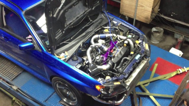
Here are some service procedures, including steps to properly remove turbocharger components, and tests and inspections you can perform to check component operation.
Subaru Turbocharger Explained: Here are some service procedures, including steps to properly remove turbocharger components, and tests and inspections you can perform to check component operation.
Intercooler Removal
You may need to remove the intercooler to work on other components beneath it. Removal of the intercooler must be performed carefully so that no damage occurs.
1.) Disconnect battery. Remove the two bolts that attach the bypass valve, then the valve.
2.) Remove the bolts from each end of the intercooler and disconnect the crankcase ventilation hoses from the intercooler.
3.) Loosen the clamps at the throttle body and outlet of the turbocharger.
4.) Gently move the intercooler side to side until the tension of the hoses at the turbocharger and throttle body loosen.
5.) Remove the intercooler from the engine compartment and cover the open areas with tape to prevent foreign material from entering, which could cause damage to the engine or turbocharger after re-installation.
2.) Remove the eight bolts that secure the protective heat shield around the turbo.
3.) Raise the vehicle and disconnect the rear oxygen sensor harness, then remove the front exhaust pipe mounting bolt. Position the pipe so there is some movement.
4.) Lower the vehicle and disconnect the wastegate hose to the vacuum hose leading to the wastegate control solenoid.
5.) Remove the coolant hose from the reservoir that connects to the turbocharger.
Turbochargers are fairly simple in concept, but adapting the system to modern vehicles can be quite complex. This primer for those new to servicing turbos and review for veterans lays out the function and operation of turbocharging in Subaru vehicles.
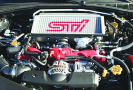
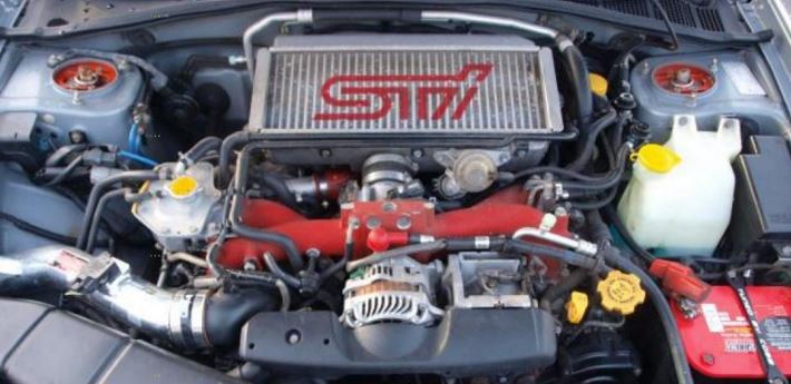
Subaru Turbocharger: Starting with 2004 models, the WRX STi incorporates a water spray system to help cool the intercooler, thereby further cooling the intake air.
The return of turbocharging in the 2002 Impreza WRX marked an absence of nearly a decade for Subaru vehicles. While the new generation has been around for half a decade, not everyone understands the function and operation of Subaru turbocharging systems.
Naturally, everyone knows these blowers are designed to get the maximum power out of engines by packing more air and fuel into the cylinders to get the biggest bang possible. Just how that is accomplished, however, may be a bit of a mystery to you. Here’s a primer on turbocharging and how it applies to Subaru vehicles.
Subaru Turbocharger Explained:
A Brief History of Turbochargers
Turbochargers were originally invented to increase the volume of air pushed into the cylinders of internal combustion engines, and, along with increased fuel, raise the level of energy produced by the combustion process
Historical references indicate that Swiss engineer Alfred J. Buchi adapted the turbines from steam engines to diesel engines as a method to improve air induction, and, therefore, smoother operation in internal combustion engines. In 1905, Buchi’s idea of powering the forced air induction by exhaust flow was granted a patent. Good idea or not, the fairly crude engines of the day could not sustain even or adequate boost pressures. Buchi worked another ten years before he could produce a working model of a turbocharged diesel engine. By that time, other companies had also produced turbocharging systems
The massive building boom of internal combustion engines to supply ships, trucks and airplanes for World War I saw technologies take a giant leap forward. The first turbocharged diesel engines for ships and locomotives appeared around 1920. Shortly thereafter, European car manufacturers began incorporating them into factory race cars and a few sporty luxury models.
The next milestone for turbocharging came with the military build-up for World War II, when turbo systems were fitted to fighter planes and bombers to allow them to fly at higher altitudes where the thinner air could be compacted into the engines to provide sufficient combustion. However, direct-driven superchargers quickly proved more reliable, efficient and more easily controlled, leaving turbochargers by the wayside.
It wasn’t until the mid-1950s when turbochargers started appearing on diesel trucks that modern turbos began to make a dent in the automotive market. Today, the vast majority of truck engines are turbodiesels.
When turbocharged vehicles began to dominate the international racing scene in the 1960s, car manufacturers began to use them in sporty models to appeal to performance-oriented drivers. By the 1980s, turbochargers for cars were a bona fide success, particularly in Subaru vehicles, due to improved metallurgy, intercooling and efficient boost controls.
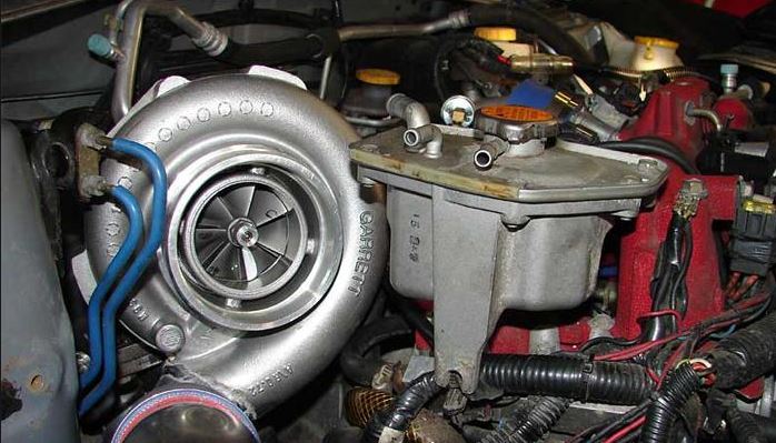
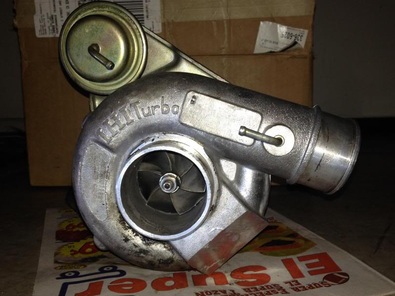
The main components of a Subaru turbocharger system are a water-cooled turbocharger, an air-cooled intercooler, a wastegate control solenoid valve, sensors and a controller. Let’s review the individual components and the role they play in the system.
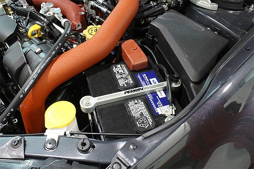
Batteries low in voltage (below 11.6 volts) need to be specially charged. A battery at this voltage is heavily sulfated and needs either a very long, slow charge, or a very high initial charge voltage.
Battery Charging Subaru: Batteries low in voltage (below 11.6 volts) need to be specially charged. A battery at this voltage is heavily sulfated and needs either a very long, slow charge, or a very high initial charge voltage.
The battery should be left on the battery charger for at least two days. Since the acid in the battery will mostly be stratified, it needs sufficient overcharge to mix. Even after a two day charge, the battery still may only come to 60-80 percent of capacity and may need to be cycled to come to full charge. If possible, once the battery is fully charged by this method, it’s advisable to finish with a constant 1 amp for an additional 24 hours.
A battery that is below 11.6 volts can also be hydrated. This means there is lead sulfate in the separator that will form lead shorts once the battery charges. Because of these shorts, the battery may self discharge once the battery has been recharged.
Emission testing of a Full-Time 4WD or all-wheel-drive vehicle must never be performed on a single two-wheel dynamometer, nor should a state I/M program inspector or its contractors install the FWD fuse in the engine compartment. Attempting to do so will result in uncontrolled vehicle movement and may cause an accident or injuries to persons nearby.
State Emission Testing Subaru: Emission testing of a Full-Time 4WD or all-wheel-drive vehicle must never be performed on a single two-wheel dynamometer.
Resultant vehicle damage due to improper testing is not covered under the SUBARU Limited Warranty and is the responsibility of the state I/M Program or its contractors or licensees.
The 1990 Clean Air Act Amendments require the Environmental Protection Agency (EPA) to implement programs to reduce air pollution from motor vehicles. Certain states are required to adopt either a “basic” or “enhanced” vehicle Inspection/Maintenance (l/M) Program, depending on the severity of their air pollution problem.
The ‘enhanced’ I/M emission testing simulates actual driving conditions on a dynamometer and permits more accurate measurement of tailpipe emissions than the ‘basic’ I/M test, which measures emissions only during engine operating conditions at idle and 2500 RPM. The ‘enhanced’ l/M test also includes a pressure check to identify evaporative emissions leaks in the fuel system.
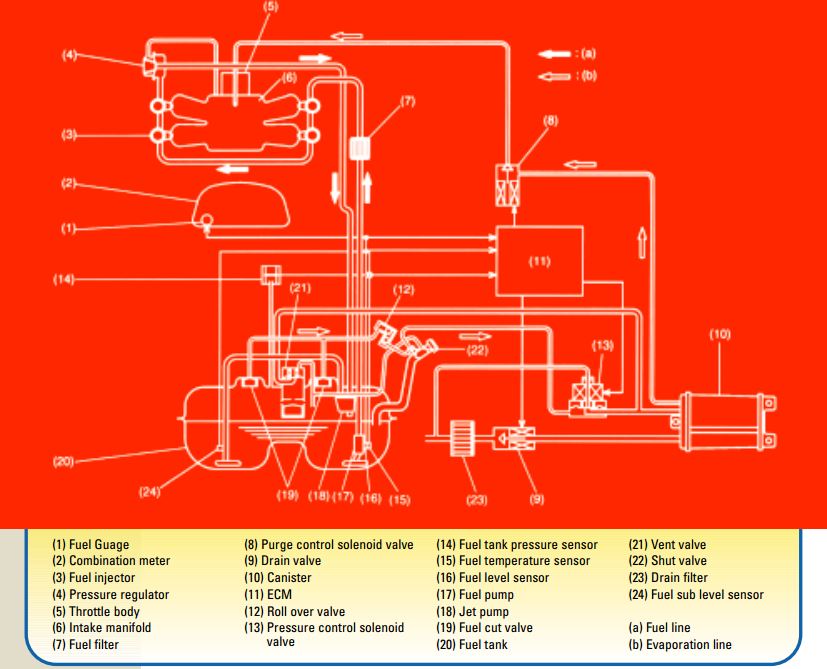
A major component of the Subaru OBD-II system is the system’s ability to monitor the evaporative emissions system. Today’s vehicles are producing very low emissions from the tailpipe, so it has become increasingly important to monitor and contain emissions from other vehicle sources.
Evaporative Emissions Testing Subaru: A major component of the Subaru OBD-II system is the system’s ability to monitor the evaporative emissions system.
A potentially large source of emissions is the vehicle’s fuel system. If not properly contained, vapors escaping from the fuel tank could produce a larger quantity of harmful emissions while the vehicle was standing still than what would be emitted via the tailpipe when the engine was running and the vehicle was driving down the road.
The Subaru OBD-II system monitors the evaporative emissions system by drawing the system to a negative pressure. If the system holds vacuum, it passes the test. If the system fails to hold vacuum for the prescribed period, it fails and a diagnostic trouble code (DTC) P04440 is stored in the ECM memory. The malfunction indicator light (MIL) also comes on in the dash to alert the driver to the problem.
The charts that follow were collected through the data link connector using the New Select Monitor (NSM), during the diagnosis of a DTC P0440 on a 1997 Subaru Legacy 2.5 liter. We’ll begin with a description of system operation under normal operating conditions.
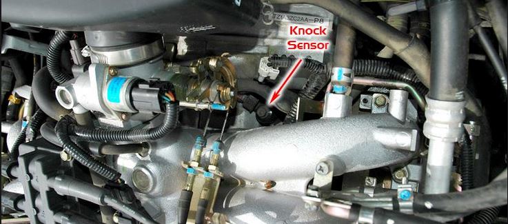
This is a simple overview on diagnosing knock sensor issues with your Subaru Impreza/Forester/Legacy/Etc.
The knock sensor is designed to sense knocking signals from each cylinder. The knock sensor is a piezo-electric type element which converts knocking vibrations into electrical signals.
The knock sensor is designed to sense knocking signals from each cylinder. The knock sensor is a piezo-electric type element which converts knocking vibrations into electrical signals. The electrical signal is sent to the ECM, which changes the ignition timing to reduce the engine knock or ping. For this system to work correctly, the knock sensor must first hear the engine ping. The driver of the vehicle may also hear a small engine ping. A delay of approximately 1-2 seconds is normal, depending on the fuel quality, engine load, air temp, etc. At this time, the ECM will retard the timing.
This function can be viewed on the Select Monitor RTRD mode. When the knock is eliminated, the timing is gradually advanced to the specified setting. If engine ping is heard again this process is repeated. This will continue until the knock sensor no longer hears the engine knock or ping.
Note: This is a normal operation of the knock sensor. Do not try to repair it.
The next page will discuss asking the right questions on diagnosing knock sensor failures.
We use cookies on our website to give you the most relevant experience by remembering your preferences and repeat visits. By clicking “Accept”, you consent to the use of ALL the cookies.
This website uses cookies to improve your experience while you navigate through the website. Out of these, the cookies that are categorized as necessary are stored on your browser as they are essential for the working of basic functionalities of the website. We also use third-party cookies that help us analyze and understand how you use this website. These cookies will be stored in your browser only with your consent. You also have the option to opt-out of these cookies. But opting out of some of these cookies may affect your browsing experience.
Necessary cookies are absolutely essential for the website to function properly. These cookies ensure basic functionalities and security features of the website, anonymously.
Cookie
Duration
Description
cookielawinfo-checkbox-analytics
11 months
This cookie is set by GDPR Cookie Consent plugin. The cookie is used to store the user consent for the cookies in the category "Analytics".
cookielawinfo-checkbox-functional
11 months
The cookie is set by GDPR cookie consent to record the user consent for the cookies in the category "Functional".
cookielawinfo-checkbox-necessary
11 months
This cookie is set by GDPR Cookie Consent plugin. The cookies is used to store the user consent for the cookies in the category "Necessary".
cookielawinfo-checkbox-others
11 months
This cookie is set by GDPR Cookie Consent plugin. The cookie is used to store the user consent for the cookies in the category "Other.
cookielawinfo-checkbox-performance
11 months
This cookie is set by GDPR Cookie Consent plugin. The cookie is used to store the user consent for the cookies in the category "Performance".
viewed_cookie_policy
11 months
The cookie is set by the GDPR Cookie Consent plugin and is used to store whether or not user has consented to the use of cookies. It does not store any personal data.
Functional cookies help to perform certain functionalities like sharing the content of the website on social media platforms, collect feedbacks, and other third-party features.
Performance cookies are used to understand and analyze the key performance indexes of the website which helps in delivering a better user experience for the visitors.
Analytical cookies are used to understand how visitors interact with the website. These cookies help provide information on metrics the number of visitors, bounce rate, traffic source, etc.
Advertisement cookies are used to provide visitors with relevant ads and marketing campaigns. These cookies track visitors across websites and collect information to provide customized ads.