The amount of force exerted on wheel bearings is astounding. Each bearing is required to smoothly control the rotation of the wheel to the tune of about a thousand revolutions per mile, support the transfer of power to the wheels for rapid starts and sudden stops, and handle the powerful lateral twisting force of the tires changing direction against the pavement — all while supporting a vertical load of hundreds of pounds. And, we expect them to perform flawlessly just about forever? Not realistic.
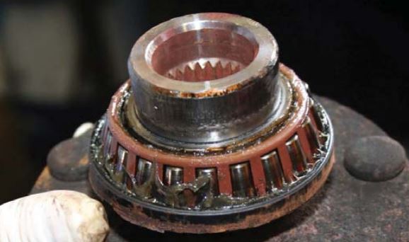
Wheel Bearing Guide Subaru: This tapered roller bearing was damaged by faulty seals that allowed water and dirt to enter the bearing.
The “Achilles Heel” of a wheel bearing is the seal. Although wheel bearings can fail due to damage, improper installation or material imperfection, the most common cause of failure is the seal losing its ability to hold the lubricating grease in and/or dirt and water out.
However, the best seal, applied to the best wheel bearing, cannot be expected to last if not correctly installed. This primer can help you properly service Subaru wheel bearings.
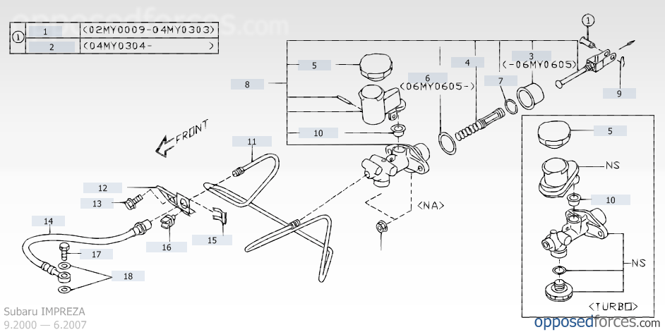
If you encounter a clutch pedal not returning completely after being engaged, or if there is a spongy or light clutch pedal feel while shifting, the following repair method should be followed.
Clutch Pedal Sticking Subaru: This condition may affect certain manual transmission vehicles with a hydraulic clutch system under certain weather conditions.
This condition may affect certain manual transmission vehicles with a hydraulic clutch system under certain weather conditions.The affected manual transmission Subaru models are as follows:
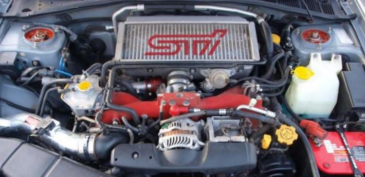
Turbochargers are fairly simple in concept, but adapting the system to modern vehicles can be quite complex. This primer for those new to servicing turbos and review for veterans lays out the function and operation of turbocharging in Subaru vehicles.
Subaru Turbocharger: Starting with 2004 models, the WRX STi incorporates a water spray system to help cool the intercooler, thereby further cooling the intake air.
The return of turbocharging in the 2002 Impreza WRX marked an absence of nearly a decade for Subaru vehicles. While the new generation has been around for half a decade, not everyone understands the function and operation of Subaru turbocharging systems.
Naturally, everyone knows these blowers are designed to get the maximum power out of engines by packing more air and fuel into the cylinders to get the biggest bang possible. Just how that is accomplished, however, may be a bit of a mystery to you. Here’s a primer on turbocharging and how it applies to Subaru vehicles.
Subaru Turbocharger Explained:
A Brief History of Turbochargers
Turbochargers were originally invented to increase the volume of air pushed into the cylinders of internal combustion engines, and, along with increased fuel, raise the level of energy produced by the combustion process
Historical references indicate that Swiss engineer Alfred J. Buchi adapted the turbines from steam engines to diesel engines as a method to improve air induction, and, therefore, smoother operation in internal combustion engines. In 1905, Buchi’s idea of powering the forced air induction by exhaust flow was granted a patent. Good idea or not, the fairly crude engines of the day could not sustain even or adequate boost pressures. Buchi worked another ten years before he could produce a working model of a turbocharged diesel engine. By that time, other companies had also produced turbocharging systems
The massive building boom of internal combustion engines to supply ships, trucks and airplanes for World War I saw technologies take a giant leap forward. The first turbocharged diesel engines for ships and locomotives appeared around 1920. Shortly thereafter, European car manufacturers began incorporating them into factory race cars and a few sporty luxury models.
The next milestone for turbocharging came with the military build-up for World War II, when turbo systems were fitted to fighter planes and bombers to allow them to fly at higher altitudes where the thinner air could be compacted into the engines to provide sufficient combustion. However, direct-driven superchargers quickly proved more reliable, efficient and more easily controlled, leaving turbochargers by the wayside.
It wasn’t until the mid-1950s when turbochargers started appearing on diesel trucks that modern turbos began to make a dent in the automotive market. Today, the vast majority of truck engines are turbodiesels.
When turbocharged vehicles began to dominate the international racing scene in the 1960s, car manufacturers began to use them in sporty models to appeal to performance-oriented drivers. By the 1980s, turbochargers for cars were a bona fide success, particularly in Subaru vehicles, due to improved metallurgy, intercooling and efficient boost controls.
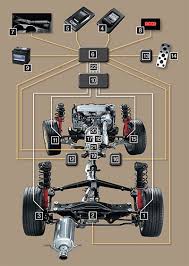
The main components of a Subaru turbocharger system are a water-cooled turbocharger, an air-cooled intercooler, a wastegate control solenoid valve, sensors and a controller. Let’s review the individual components and the role they play in the system.
This is a step by step guide on installing steering rack bushings (whiteline) on a 08+ WRX/STi. This needs to be done the right way and all the bolts NEED to be torqued with a torque wrench to factory spec for the car to be in a safe operating state.
1.) Remove the under tray. There are 2 12mm bolts towards the front, 1 12mm bolt on the rear, 2 clips on the rear. and 2 plastic pop-out clips on the sides near each wheel well.
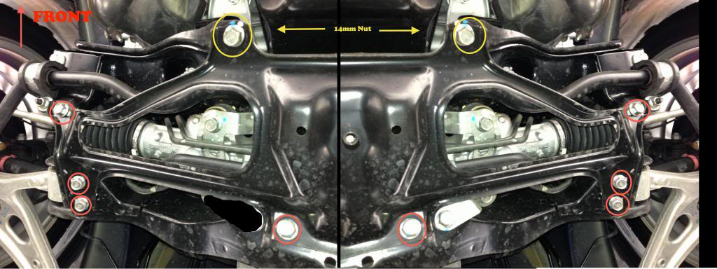
2.) After removing the under tray you will need to remove 10 14mm bolts holding the cross member support brace (otherwise known as the jack plate) in place. The bolts that are to be removed are circled in red and yellow.
Note: The bolts circled in yellow are secured by nuts on the topside so you will need the 14mm wench as well. These bolts are torqued down pretty tight if they have never been removed before.
Steering Rack Bushings Install on a 08+ STi: The bolts circled in yellow are secured by nuts on the topside so you will need the 14mm wench as well.
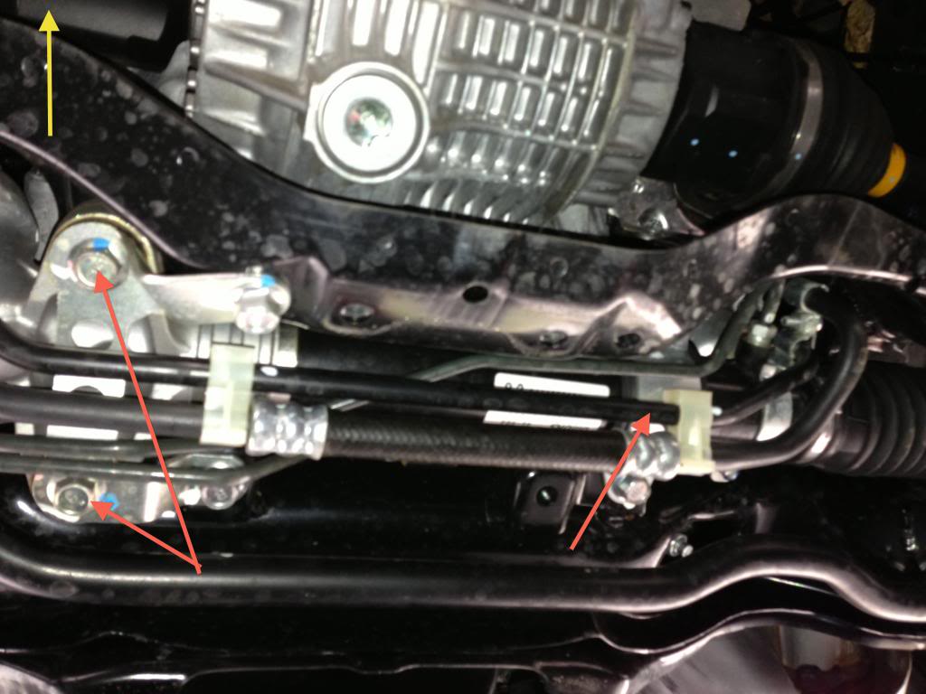
3.) Once the cross member support is removed the steering rack will be exposed as pictured below. Note the location of the 3 bushings denoted by the red arrows.
Steering Rack Bushings Install on a 08+ STi: Note the location of the 3 bushings denoted by the red arrows.
Subaru’s power steering system contains a pump, hydraulic line, and a gearbox (rack). The hydraulic pump is a vane-type pump driven by the engine. It provides pressurized fluid for the system.
Power Steering Systems On Early Subarus Part 2: Subaru’s power steering system contains a pump, hydraulic line, and a gearbox (rack). The hydraulic pump is a vane-type pump driven by the engine. It provides pressurized fluid for the system.
Oil Pump Operation
The pump has two internal valves: a flow control valve and a relief valve. The flow control valve regulates the volume of power steering fluid delivered to the rack. During high engine rpm, the pressure in the pump overcomes the flow control valve spring. The control valve slides back to close off an oil passage to the rack and to open an oil return port to the pump inlet. This reduces the power assist to the rack during high speeds, improving the steering wheel feel and response.
ABS 5.3 Antilock Brake System for Early Subaru Part 5:
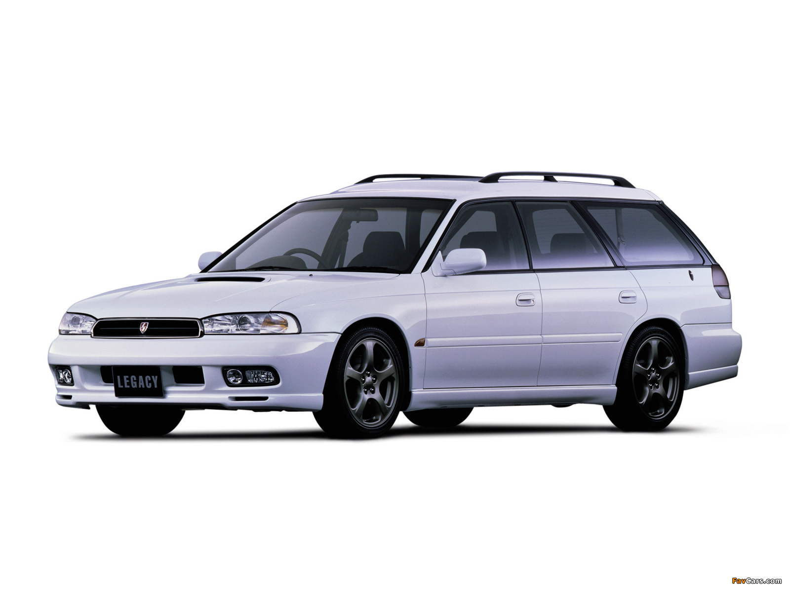
ABS 5.3 Antilock Brake System for Early Subaru Part 5: Beginning in approximately December of 1996, a new antilock braking system called ABS 5.3 was installed on Legacy vehicles equipped with ABS.
Beginning in approximately December of 1996, a new antilock braking system called ABS 5.3 was installed on Legacy vehicles equipped with ABS. This system uses a Bosch hydraulic control unit and a Nippon electronic control unit. ABS 5.3 is a four channel control design which can independently control the front wheels and utilize select low control to control the rear wheels (a system which provides the same fluid pressure control for the two rear wheels if either wheel starts to lock up).
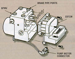
Although similar to other Subaru ABS systems, there have been enhancements to component operation and location. Diagnosis has also improved because of the ability of the 5.3 ABS system to communicate with the Select Monitor. The hydraulic control unit or HCU is located under the hood on the right side of the engine compartment. The size of the HCU has decreased by approximately a third from that of the ABS-2E system, used on previous model year vehicles.
The HCU controls brake fluid flow by utilizing eight solenoid valves. There is an inlet solenoid valve and an outlet solenoid valve for each wheel. Mechanically, the inlet solenoid valve is open during normal braking, and the outlet solenoid valve is closed. The HCU also contains a motor and pump assembly, which operates only while ABS is actively controlling the brake fluid flow–preventing a wheel lock.
ABS 5.3: Beginning in approximately December of 1996, a new antilock braking system called ABS 5.3 was installed on Legacy vehicles equipped with ABS.
Externally the HCU of the ABS 5.3 has a relay box attached. This allows troubleshooting of the valve and motor relay area to be kept separate from the troubleshooting of the solenoid valves and pump motor. There are four modes of operation for the ABS 5.3 system. They are normal, pressure-drop, pressure-hold and pressure-increase. When wheel lockup is sensed, Mode Two, Mode Three and Mode Four may be activated. They are described as follows:
Steering and suspension parts are a lot like the brake system components. Their proper operation is vitally important to the safety of the driver and his passengers, but it is very difficult to determine how long it will be before any of these components will require attention. That’s why an inspection of all steering and suspension components is required at 15 month/15,000 mile intervals. Changes to these systems may be too gradual for the driver to even notice, leaving it to you to ferret out and correct any wear or damage that has taken place.
Maintenance:Subaru Periodic Maintenance Part 4: Regular checks of the steering and suspension is important.
We won’t cover all of the steering and suspension checks here. There’s too much variation between different Subaru models to do an adequate job. What you’re looking for is anything that reduces the original precision of the steering and suspension systems. Perhaps the steering has a little too much play in it or the shocks and struts don’t handle the bumps in the road as well as they did when new. Specific tests for the Subaru model you’re working on can be found in the service manual.
Check the power steering system for dampness or other signs of fluid leakage. The power steering pump reservoir is a good place to start. If the reservoir is low, the fluid has probably leaked out, as it has no place else to go. Approved fluids for the power steering system include Dexron II, IIE or III.
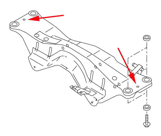
This is a step by step guide on installing a subframe lockbolt kit into the rear subframe of your 02-07 Subaru Impreza WRX/STi.
Subframe Lockbolt install for Subaru WRX/STi: Where these two red arrows point to are where the lockout bolts will be installed.
The rear subframe is isolated by rubber bushings which allow some movement relative the WRX/STi chassis. This movement can be the source of a rubbery feeling during launch and hard cornering. Enough rear subframe movement may alter the rear toe settings and affect handling during advanced driving. Depending on which lockbolt brand you use the adapter portion may not sit flush to the subframe surface, this is part of the design and is OK.
The lockbolt is not designed to stop vertical movement of the rear subframe. It is meant to limit movement in the horizontal plane. PB Blaster will soften the factory undercoating spray thus making a mess. WD-40 is not as aggressive so less black mess is made.
We use cookies on our website to give you the most relevant experience by remembering your preferences and repeat visits. By clicking “Accept”, you consent to the use of ALL the cookies.
This website uses cookies to improve your experience while you navigate through the website. Out of these, the cookies that are categorized as necessary are stored on your browser as they are essential for the working of basic functionalities of the website. We also use third-party cookies that help us analyze and understand how you use this website. These cookies will be stored in your browser only with your consent. You also have the option to opt-out of these cookies. But opting out of some of these cookies may affect your browsing experience.
Necessary cookies are absolutely essential for the website to function properly. These cookies ensure basic functionalities and security features of the website, anonymously.
Cookie
Duration
Description
cookielawinfo-checkbox-analytics
11 months
This cookie is set by GDPR Cookie Consent plugin. The cookie is used to store the user consent for the cookies in the category "Analytics".
cookielawinfo-checkbox-functional
11 months
The cookie is set by GDPR cookie consent to record the user consent for the cookies in the category "Functional".
cookielawinfo-checkbox-necessary
11 months
This cookie is set by GDPR Cookie Consent plugin. The cookies is used to store the user consent for the cookies in the category "Necessary".
cookielawinfo-checkbox-others
11 months
This cookie is set by GDPR Cookie Consent plugin. The cookie is used to store the user consent for the cookies in the category "Other.
cookielawinfo-checkbox-performance
11 months
This cookie is set by GDPR Cookie Consent plugin. The cookie is used to store the user consent for the cookies in the category "Performance".
viewed_cookie_policy
11 months
The cookie is set by the GDPR Cookie Consent plugin and is used to store whether or not user has consented to the use of cookies. It does not store any personal data.
Functional cookies help to perform certain functionalities like sharing the content of the website on social media platforms, collect feedbacks, and other third-party features.
Performance cookies are used to understand and analyze the key performance indexes of the website which helps in delivering a better user experience for the visitors.
Analytical cookies are used to understand how visitors interact with the website. These cookies help provide information on metrics the number of visitors, bounce rate, traffic source, etc.
Advertisement cookies are used to provide visitors with relevant ads and marketing campaigns. These cookies track visitors across websites and collect information to provide customized ads.