One of the most common concerns that any vehicle owner perceives as a problem is brake noise when stopping the vehicle. The question pops up: “What is considered to be an ‘acceptable’ level of brake noise?”
Brake Noise Is It Normal? One of the most common concerns that any vehicle owner perceives as a problem is brake noise when stopping the vehicle.
The disc brake systems used on vehicles today are designed and developed to meet many different, but very strict requirements. This must be accomplished while providing an optimum level of performance under a wide range of vehicle and environmental operating conditions.
The brake pads selected must be a balanced choice. There is a fine line between a quiet brake pad and one that will provide optimum performance under extreme braking conditions. Consequently, when a change is made in the brake pad formulation (whether it is meant to provide longer pad life, shorter stopping distances, noise reduction or a change in pedal effort), a trade-off must be made in one area or another.
An example of pad formulation change would be the industry’s switch from asbestos to semi-metallic brake linings.
ABS 5.3 Antilock Brake System for Early Subaru Part 5:
ABS 5.3 Antilock Brake System for Early Subaru Part 5: Beginning in approximately December of 1996, a new antilock braking system called ABS 5.3 was installed on Legacy vehicles equipped with ABS.
Beginning in approximately December of 1996, a new antilock braking system called ABS 5.3 was installed on Legacy vehicles equipped with ABS. This system uses a Bosch hydraulic control unit and a Nippon electronic control unit. ABS 5.3 is a four channel control design which can independently control the front wheels and utilize select low control to control the rear wheels (a system which provides the same fluid pressure control for the two rear wheels if either wheel starts to lock up).
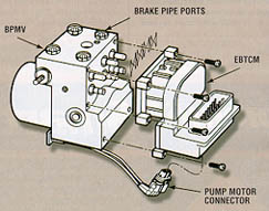
Although similar to other Subaru ABS systems, there have been enhancements to component operation and location. Diagnosis has also improved because of the ability of the 5.3 ABS system to communicate with the Select Monitor. The hydraulic control unit or HCU is located under the hood on the right side of the engine compartment. The size of the HCU has decreased by approximately a third from that of the ABS-2E system, used on previous model year vehicles.
The HCU controls brake fluid flow by utilizing eight solenoid valves. There is an inlet solenoid valve and an outlet solenoid valve for each wheel. Mechanically, the inlet solenoid valve is open during normal braking, and the outlet solenoid valve is closed. The HCU also contains a motor and pump assembly, which operates only while ABS is actively controlling the brake fluid flow–preventing a wheel lock.
ABS 5.3: Beginning in approximately December of 1996, a new antilock braking system called ABS 5.3 was installed on Legacy vehicles equipped with ABS.
Externally the HCU of the ABS 5.3 has a relay box attached. This allows troubleshooting of the valve and motor relay area to be kept separate from the troubleshooting of the solenoid valves and pump motor. There are four modes of operation for the ABS 5.3 system. They are normal, pressure-drop, pressure-hold and pressure-increase. When wheel lockup is sensed, Mode Two, Mode Three and Mode Four may be activated. They are described as follows:
To troubleshoot ABS systems, it’s best to follow a step-by-step procedure like the one on the 1992 Legacy ABS-2E Service Manual Supplement. Enter the flow diagram with the symptom reported on the repair order.
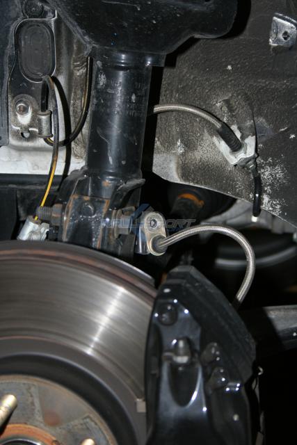
ABS Brake System for Early Subaru Part 4: The Subaru Legacy RS was known for using this ABS System.
The diagram calls that Trouble Occurs. The first step in the procedure is “Basic Checks.” This calls for a visual inspection to look for obvious problems and includes the following items:
• improper battery voltage
• low brake fluid level
• brake fluid leaks
• brake drag
• condition of the brake pads and rotors
• size, type, and condition of the tires (Check the tires to confirm that they are the correct tires for the vehicle, that they are in good condition, and that they are inflated to the correct pressure).
If you find something wrong at this stage, correct it and see whether it eliminates the reported symptom. If not, continue to Step 3. Step 3 is Self-diagnosis. At this time, put the ECU into self-diagnostic mode, and monitor the ABS warning lamp for trouble codes.
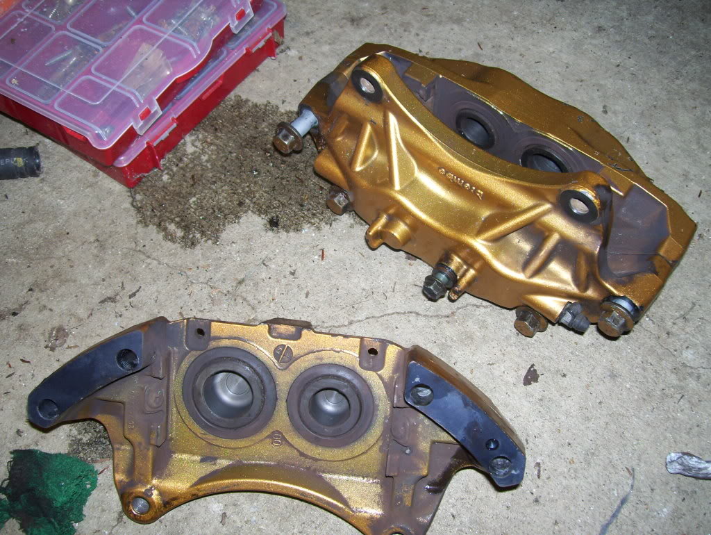
A step by step guide to rebuilding a Brembo caliper with rebuild kits. This guide includes separating the calipers as well if you want to go that route:
1.) If you have not yet removed calipers from the car remove them, I cleaned mine prior to starting. You will need to disconnect the brake lines and unbolt them from the hub. Also remove the pads, to remove the pads there are 2 pull pin clips thru a set of long pins. The pins hold the pad and metal bracket in place. Remove the 2 pull pins and slide out the 2 longer pins and everything will fall out. Keep in mind there are small plates on the back sides of the brake pads where the pistons hit the pad, these can be easily lost and are marked with arrows for direction.
2.) You then need to split the calipers apart, to do this I used a impact wrench but if you have some good strength it is possible to break the bolts. Pretty sure the bolts on the front are a 13mm and the rears use a allen wrench style bolt which i believe is a size 6.
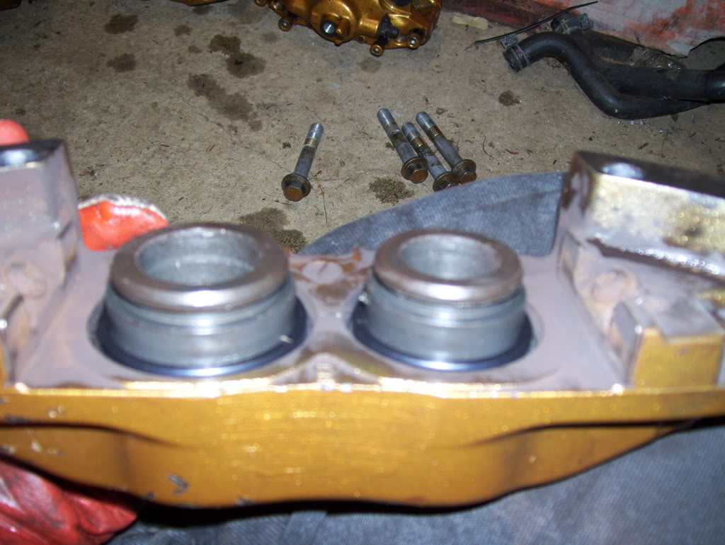
3.) You will want to pop the pistons out. In order to do this I used, for the rear a inch by 5 inch block of wood, for the front you will need a little thicker of a block. Place the block where the rotor would sit so that the piston doesn’t shoot out and kill someone. (trust me these things will FLY) After doing this i made sure my bolts were very lightly tightened into place, I did this because if you leave the gap the pistons will put force in the way of least resistance which basically means its going to shoot the caliper apart and split it which could cause some pain.
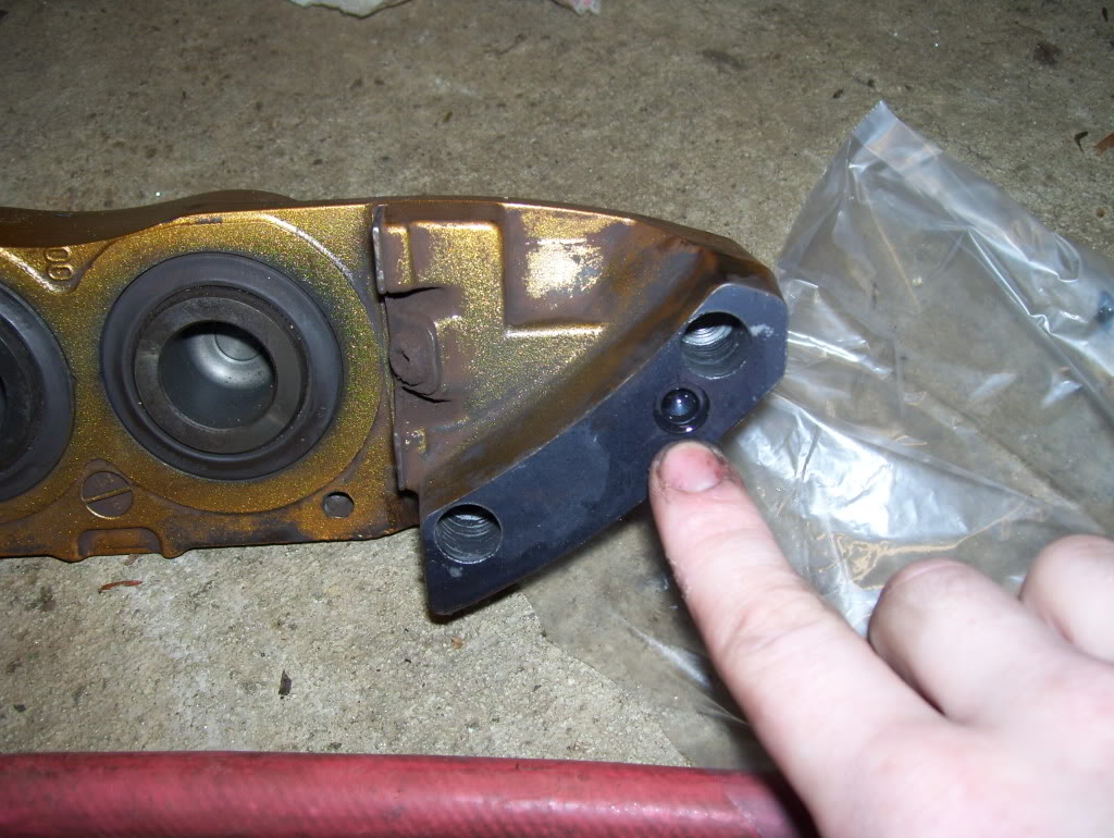
4.) After splitting the calipers and popping the pistons I removed the rubber seal between the 2 pieces as it is small and could very easily be lost. Don’t remove the o-ring prior to step 3 or step 3 is pretty much impossible.
Brembo Caliper: O-Ring removed.Brembo Caliper: O-ring location in a brembo caliper.
The brake master cylinder is located by the driver’s side strut tower and once you find it the rest is pretty self explanatory. I have a 2005 Subaru STi. Some later years might be slightly different.
Tools needed:
10 mm socket and wrenches
Zip tie (optional)
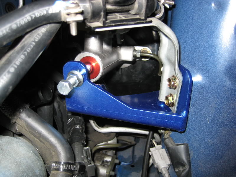
Master Cylinder Brace: A installed Cusco master cylinder brace.
1.) Find the brake master cylinder located just inboard of the drivers side strut tower. The washer fluid bottle will be in the way so unbolt the two bolts and lean it forward, no need to disconnect it altogether.
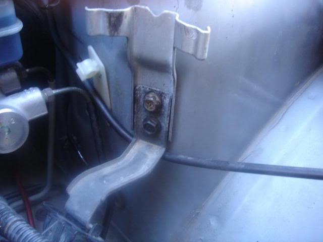
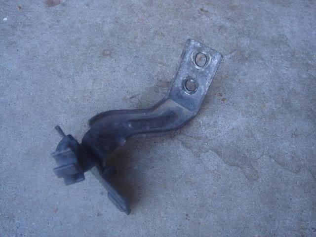
2.) There are two brackets bolted to the strut tower visible in this picture. These are the two holes used to mount the brace. Unbolt these two holes.
Master Cylinder Brace: There are two brackets bolted to the strut tower visible in this picture.
3.)The lower bracket is not compatible with the master cylinder brace. Its best to remove the bracket, then zip tie the lines to the master cylinder brace at the end to keep them secure.
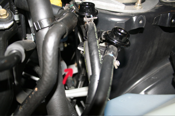
4.)The next bolt to take out is difficult to get a picture of but you will see it easily you can barely see it here, it is located slightly farther towards the back of the car, undo it as well.
Master Cylinder Brace: The hidden bolt is located slightly farther towards the back of the car, undo it as well.
We use cookies on our website to give you the most relevant experience by remembering your preferences and repeat visits. By clicking “Accept”, you consent to the use of ALL the cookies.
This website uses cookies to improve your experience while you navigate through the website. Out of these, the cookies that are categorized as necessary are stored on your browser as they are essential for the working of basic functionalities of the website. We also use third-party cookies that help us analyze and understand how you use this website. These cookies will be stored in your browser only with your consent. You also have the option to opt-out of these cookies. But opting out of some of these cookies may affect your browsing experience.
Necessary cookies are absolutely essential for the website to function properly. These cookies ensure basic functionalities and security features of the website, anonymously.
Cookie
Duration
Description
cookielawinfo-checkbox-analytics
11 months
This cookie is set by GDPR Cookie Consent plugin. The cookie is used to store the user consent for the cookies in the category "Analytics".
cookielawinfo-checkbox-functional
11 months
The cookie is set by GDPR cookie consent to record the user consent for the cookies in the category "Functional".
cookielawinfo-checkbox-necessary
11 months
This cookie is set by GDPR Cookie Consent plugin. The cookies is used to store the user consent for the cookies in the category "Necessary".
cookielawinfo-checkbox-others
11 months
This cookie is set by GDPR Cookie Consent plugin. The cookie is used to store the user consent for the cookies in the category "Other.
cookielawinfo-checkbox-performance
11 months
This cookie is set by GDPR Cookie Consent plugin. The cookie is used to store the user consent for the cookies in the category "Performance".
viewed_cookie_policy
11 months
The cookie is set by the GDPR Cookie Consent plugin and is used to store whether or not user has consented to the use of cookies. It does not store any personal data.
Functional cookies help to perform certain functionalities like sharing the content of the website on social media platforms, collect feedbacks, and other third-party features.
Performance cookies are used to understand and analyze the key performance indexes of the website which helps in delivering a better user experience for the visitors.
Analytical cookies are used to understand how visitors interact with the website. These cookies help provide information on metrics the number of visitors, bounce rate, traffic source, etc.
Advertisement cookies are used to provide visitors with relevant ads and marketing campaigns. These cookies track visitors across websites and collect information to provide customized ads.