Tag Archives: gc8

DCCD Subaru STi Explained

DCCD Subaru STi Explained:

The Driver’s Control Center Differential system is system that appropriately controls the differential limiting force of center differential LSD depending on running conditions of a vehicle. The DCCD system evolved provides controls that follow operations of the driver, while conventional DCCD system provides those based on conditions of the vehicle.

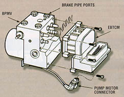
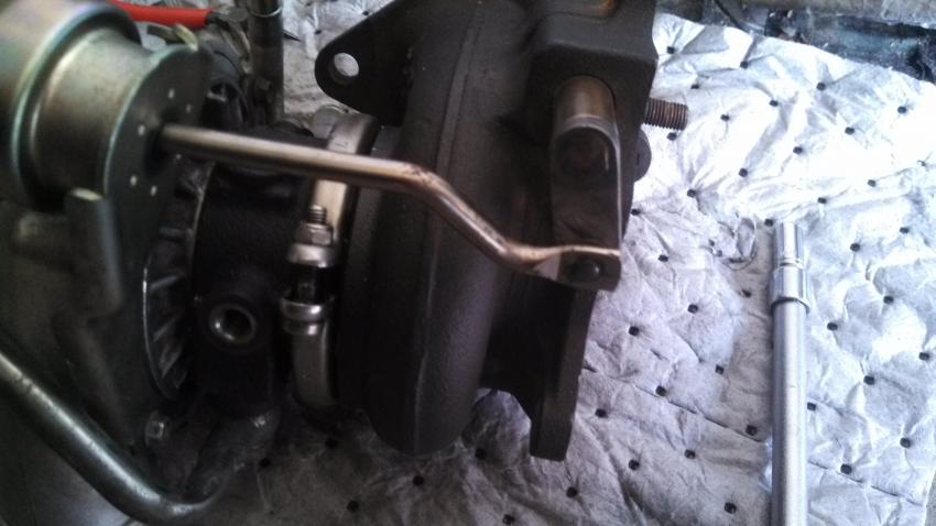
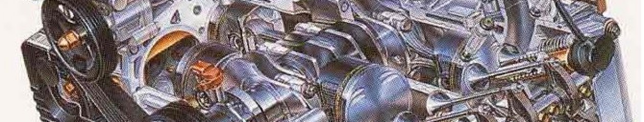
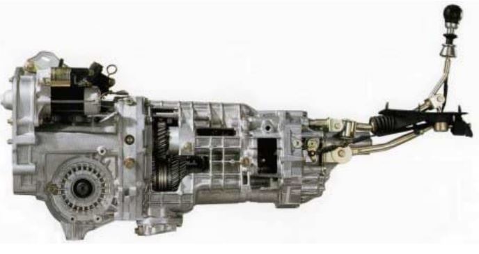
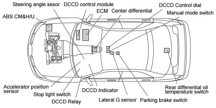
The system consists of a center differential of planetary gear type provided with LSD function, a steering angle sensor, a yaw rate sensor, a lateral G sensor, a DCCD control module and other components.

DCCD: The DCCD system evolved provides controls that follow operations of the driver, while conventional DCCD system provides those based on conditions of the vehicle.

Hybrid LSD mechanism using conventional electromagnetic clutch LSD mechanism added with torque-sensitive mechanical LSD mechanism allows approximate coincidence between the vehicle acceleration/deceleration and LSD clutch differential limiting timings, resulting in linear LSD characteristics acquired through driver’s accelerator operation. Thus, the driver can more freely control the vehicle by easily grasping behavior of the vehicle.

In addition, the steering angle sensor let the DCCD control module know the driver’s intension of turning. In combination with the yaw rate and lateral G sensors, it adjusts the electromagnetic clutch LSD differential limiting force based on the running path imaged by the driver and the actual behavior of the vehicle. Thus, cornering in better accordance with the driver’s image is enabled, preventing occurrence of understeer and oversteer.

LSD MECHANICAL DCCD ADVANTAGE EXPLAINED

For balancing between the vehicle turning performance and traction during turning in a high order, the center differential driving torque is set to have distribution ratio 41:59.


DCCD: For balancing between the vehicle turning performance and traction during turning in a high order, the center differential driving torque is set to have distribution ratio 41:59.
DCCD: For balancing between the vehicle turning performance and traction during
turning in a high order, the center differential driving torque is set to have distribution ratio 41:59.


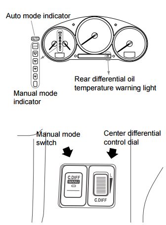
Manual mode switch/DCCD control dial

In manual mode, the DCCD control can be used to adjust the differential limiting force of the electromagnetic clutch LSD mechanism in the range from free to lock. Current settings of the control dial are displayed on the indicator in the meter.

DCCD: In manual mode, the DCCD control can be used to adjust the differential limiting force of the electromagnetic clutch LSD mechanism in the range from free to lock.
DCCD: In manual mode, the DCCD control can be used to adjust the differential limiting force of the electromagnetic clutch LSD mechanism in the range from free to lock.


NEXT PAGE

Electrical Grounding System inspection

Electrical Grounding System inspection:

The importance of checking electrical ground connections during any electrical troubleshooting cannot be over stressed. For example, a poor electrical ground at the radiator support or fender (depending on the affected Subaru model) may cause any or all of the following problems:

• The door ajar indicator light dims when the brake pedal is applied.

• There is a loss of communication with the Automatic Transmission side of the New Select Monitor when the vehicle is put into gear.

• The engine starts running poorly after driving only a few feet.

• There is a loss of communication with the Anti-lock Brake side of the New Select Monitor when the brake pedal is applied.

Vehicles that have been involved in accidents should be inspected especially closely. In the example below, a Subaru Legacy had been involved in a front end collision.

During reassembly of the vehicle, the electrical ground wire behind the left front headlight that fastens to the radiator support had not been reinstalled (refer to photo). This electrical ground is attached to the left front fender on Subaru Impreza and Forester models. After reinstalling this ground wire, all of the affected systems returned to proper working order.

Electrical Grounding System inspection: The importance of checking ground connections during any electrical troubleshooting cannot be over stressed.
Electrical Grounding System inspection: The importance of checking ground connections during any electrical troubleshooting cannot be over stressed.


Wheel Alignment For Subarus:

Wheel Alignment For Subaru:

Wheel arch height (vehicle ride height) as well as front and rear wheel alignment should be inspected at 30 month/30,000 mile intervals. Winter driving and its attendant chuckholes may shorten that maintenance interval for some drivers

While inspecting wheel alignment, also check for obvious signs of damage to suspension components, tightness of bolts and nuts and the condition of other under car components.

Check, adjust and/or measure wheel alignment in accordance with the following procedures:

1.) Wheel arch height (front and rear)
2.) Camber (front and rear)
3.) Caster (front)
4.) Front toe-in
5.) Rear toe-in
6.) Thrust angle (rear)
7.) Wheel steering angle

1. Wheel Arch Height

1.) Adjust the tire pressures to specifications.
2.) Set the vehicle under “curb weight” conditions (empty luggage compartment, install spare tire, jack, service tools, and top off fuel tank).
3.) Set steering wheel in a wheel-forward position.
4.) Suspend a thread from the wheel arch (point “A” in figure above) to determine a point directly above the center of the spindle.

Subaru Wheel Alignment: Measure the distance between the measuring point and the center of the spindle.

5.) Measure the distance between the measuring point and the center of the spindle.
6.) Consult the service manual for Wheel Arch Height specifications.

SVX POWER STEERING SYSTEMS PART 4

SVX Power Steering Systems on Early Subarus Part 4:

There are two model-specific systems available on SVX vehicles:

SVX Power Steering Systems on Early Subarus Part 4: The engine speed sensitive, or conventional belt driven hydraulic pump and pinion type steering system is standard equipment on the SVX.

• The engine speed sensitive, or conventional belt driven hydraulic pump and pinion type steering system is standard equipment on the SVX.

• An SVX equipped with the SVX Touring Package uses an optional vehicle speed-sensitive system. This system provides normal power assist at low vehicle speeds for reduced driver steering effort, and reduced steering assist at increased vehicle speeds for increased road feel and improved engine operating efficiency. Both systems have many similarities with the Legacy system.

SVX Power Steering Pump

Both systems share many similarities to existing Subaru steering systems. Both use a belt driven power steering pump, although the pump housings are different in appearance.

Rack

A conventional power assisted rack with the standard Subaru lines and hoses is used by the standard system.

Oil Cooler

An oil cooler pipe has been added to both SVX systems. It is located in front of the radiator on the return side of the system.

Rubber Coupler

A steering shaft rubber coupler is used by both SVX systems to reduce road noise and vibration.

SVX Power Steering Pressure Switch

A power steering pressure switch is located on the outlet side of the pump. The switch monitors increased engine load during idle speed steering. The switch provides an input to the MPFI ECU, which prevents stalling by raising the engine idle speed. There is not an additional trouble code for the MPFI ECU.

Steering Systems on early Subarus Part 1

Steering Systems on early Subarus Part 1:

Rack And Pinion Steering Mechanism

Subaru steering systems utilize a rack and pinion steering mechanism. As the pinion gear rotates, the rack moves left or right. Rack and pinion steering gives the driver precise control over the wheels. The simple, compact design is easy to service.

Steering Systems on early Subarus Part 1: The Subaru SVX used Subaru's early power steering system.
Steering Systems on early Subarus Part 1: The Subaru SVX used Subaru’s early power steering system.

CGR – VGR Ratios

Two manual steering racks are used in Subaru vehicles: a constant gear ratio (CGR) rack and a variable gear ratio (VGR) rack. The teeth on the CGR rack are equally spaced so the turning effort is equal throughout the turning range. The teeth on the VGR rack are spaced closer together on the ends of the rack than in the middle. The turning effort decreases as the turning angle increases so sharp-radius turns are easier to make.

Legacy and SVX Steering Racks

Several different power steering racks have been installed in Subaru vehicles. The racks used in the L-series, XT, Legacy and SVX vehicles are similar. All have a one-piece gearbox and lack the external air vent distribution tube found on the rack in pre-’85 and carryover vehicles. However, the XT rack differs from the L-series rack in several ways.

The XT rack is made of aluminum and has a different control valve. Different types of hydraulic seals are used in the two racks, and each has its own unique special service tool. The power steering rack in the pre-’85 model year vehicles and the Brat has a two-piece gearbox and an air vent distribution tube. It also has seals, service procedures and special service tools that differ from the other racks.

Rigid Steering Column

Three types of steering columns are used in Subaru vehicles: a rigid steering column, a tilt steering column and the XT and SVX tilt and telescoping steering column. The rigid steering column is found on L-series DL models, the Legacy standard model, and Justy vehicles. The rigid steering shaft does not tilt or pop-up, but is collapsible (a safety feature). The shaft is connected to the gearbox by universal joints.

ABS 5.3 Antilock Brake System for Early Subaru Part 5:

ABS 5.3 Antilock Brake System for Early Subaru Part 5:


ABS 5.3 Antilock Brake System for Early Subaru Part 5: Beginning in approximately December of 1996, a new antilock braking system called ABS 5.3 was installed on Legacy vehicles equipped with ABS.
ABS 5.3 Antilock Brake System for Early Subaru Part 5:
Beginning in approximately December of 1996, a new antilock braking system called ABS 5.3 was installed on Legacy vehicles equipped with ABS.


Beginning in approximately December of 1996, a new antilock braking system called ABS 5.3 was installed on Legacy vehicles equipped with ABS. This system uses a Bosch hydraulic control unit and a Nippon electronic control unit. ABS 5.3 is a four channel control design which can independently control the front wheels and utilize select low control to control the rear wheels (a system which provides the same fluid pressure control for the two rear wheels if either wheel starts to lock up).

Although similar to other Subaru ABS systems, there have been enhancements to component operation and location. Diagnosis has also improved because of the ability of the 5.3 ABS system to communicate with the Select Monitor. The hydraulic control unit or HCU is located under the hood on the right side of the engine compartment. The size of the HCU has decreased by approximately a third from that of the ABS-2E system, used on previous model year vehicles.

The HCU controls brake fluid flow by utilizing eight solenoid valves. There is an inlet solenoid valve and an outlet solenoid valve for each wheel. Mechanically, the inlet solenoid valve is open during normal braking, and the outlet solenoid valve is closed. The HCU also contains a motor and pump assembly, which operates only while ABS is actively controlling the brake fluid flow–preventing a wheel lock.

Beginning in approximately December of 1996, a new antilock braking system called ABS 5.3 was installed on Legacy vehicles equipped with ABS.
ABS 5.3: Beginning in approximately December of 1996, a new antilock braking system called ABS 5.3 was installed on Legacy vehicles equipped with ABS.

Externally the HCU of the ABS 5.3 has a relay box attached. This allows troubleshooting of the valve and motor relay area to be kept separate from the troubleshooting of the solenoid valves and pump motor. There are four modes of operation for the ABS 5.3 system. They are normal, pressure-drop, pressure-hold and pressure-increase. When wheel lockup is sensed, Mode Two, Mode Three and Mode Four may be activated. They are described as follows:

Wastegate and Boost Creep FAQ

Wastegate and Boost Creep FAQ

What is Boost Creep?

Boost creep is a situation where your wastegate port is not large enough to allow the exhaust gas to bypass the turbo. What happens is the exhaust gas will choke the wastegate port preventing further gas flow through the port. Then, the exhaust gas has to take the path of least resistance which is through the turbine of the turbo. This will spool the turbo ‘uncontrolled’ beyond your normal controlled max boost level.

Wastegate and Boost Creep FAQ: A stock Subaru turbo with the internal wastegate and stock actuator.
Wastegate and Boost Creep FAQ: A stock Subaru turbo.

The turbo will be spooling past wastegate spring rate pressure even though the wastegate is fully open thus it is uncontrolled. The best way to check for boost creep is to connect the turbo outlet port directly to the wastegate actuator port and go for a drive. In 4th gear you should normally get a stable boost level of about 0.5 BAR, if you have boost creep the boost will hit 0.5 BAR and will continue to rise with rpm until you either back off or hit overboost fuel cut.

Boost creep should only be present on a turbo that has very little restriction. For example a fully de-catted and high flow induction. It’s been found that the fast spooling IHI VF35 is very prone to boost creep. The cure is to remove the turbo and enlarge the wastegate port. Then, fit a stronger actuator 0.75 BAR the reason for this is because you have made the wastegate port larger. The effective size of the wastegate plate acting against the exhaust gas flow is larger which allows the exhaust gas excert more force on the wastegate plate.

This in effect weakens the effectiveness of the actuator. Before the increase in size of your wastegate port the actuator would open at 0.5 BAR, after the increase the actuator would open earlier at 0.3–0.4 BAR. After these changes are made to the turbo either a boost controller or a remap (to adjust solenoid duty cycle) should be sought to control the boost to a safe level.

Headlight aiming basics for Subarus:

Headlight aiming basics for Subarus:

Subaru models equipped with aerodynamic headlights require no special fixtures for headlight alignment. Each headlight is equipped with a built-in headlight aiming mechanism. The following sequence demonstrates the correct technique for adjusting the headlights on a Subaru Legacy equipped with aerodynamic headlights.

Headlight aiming basics for Subarus: Some basic headlight adjusting techniques for Subaru cars.

1.) Turn off the headlight before adjusting headlight aiming. If the light is necessary to check aiming, do not turn on the headlights for more than two minutes.

2.) Inspect the area around the headlight for any damage. If the vehicle has been involved in an accident, it may not be possible to properly adjust the headlights until the damage has been professionally repaired.

3.)The vehicle must be parked on level ground and all four tires must be properly inflated.