Subaru OBD2 Decoding Explained

Subaru OBD2 Decoding

Few types of diagnostic trouble codes can be more confusing than those dealing with emission problems. From the beginning of mandatory Subaru OBD2 in 1996, more codes have been added and some have changed. Here’s a look at how Subaru of America, Inc. has added and streamlined P0400-series DTCs.
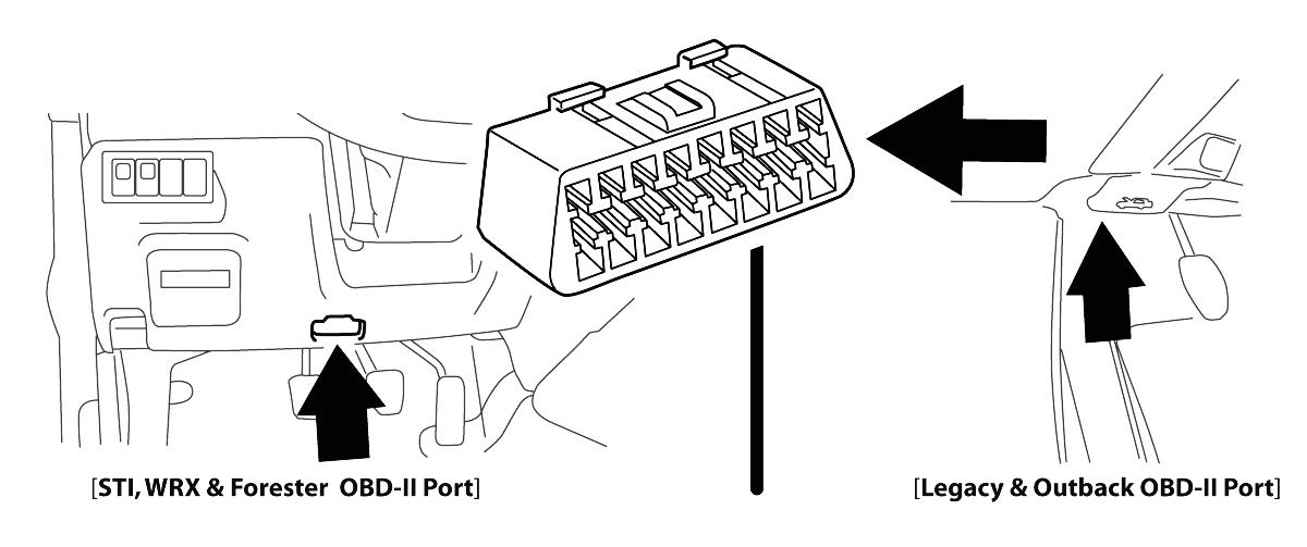
Subaru OBD2 Decoding: Locations of the OBD2 ports in various Subaru cars.

Emissions-related Subaru OBD2 diagnostic trouble codes (DTCs) have evolved over the last dozen years to more precisely pinpoint the problems in automotive systems. The handful of emissions codes used for On-Board Diagnostic (OBD) systems on the late 1980s and early 1990s has grown to nearly a hundred today. Over that time, many DTCS have been modified to more accurately reflect the cause, while others have been added to the list to address issues with advancing technology.

In order to understand how these factors affect Subaru OBD2 vehicles, it’s necessary to first look at the history of emissions control, on-board diagnostics and the DTC coding system.

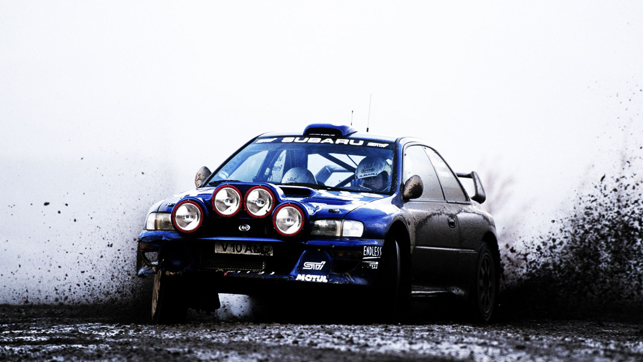
Subaru Picture of the day!

AWD: The Impreza WRX STI uses Driver Controlled Center Differential (DCCD), the most performance-directed type of Symmetrical AWD. A limited-slip, planetary gear-type center differential provides a performanceoriented 35:65 front/rear power split.

AWD: The Impreza WRX STI uses Driver Controlled Center Differential (DCCD), the most performance-directed type of Symmetrical AWD. A limited-slip, planetary gear-type center differential provides a performanceoriented 35:65 front/rear power split.

AWD: The Impreza WRX STI uses Driver Controlled Center Differential (DCCD), the most performance-directed type of Symmetrical AWD. A limited-slip, planetary gear-type center differential provides a performanceoriented 35:65 front/rear power split.

Wheel Bearing Guide Subaru

Wheel Bearing Subaru Guide:

The amount of force exerted on wheel bearings is astounding. Each bearing is required to smoothly control the rotation of the wheel to the tune of about a thousand revolutions per mile, support the transfer of power to the wheels for rapid starts and sudden stops, and handle the powerful lateral twisting force of the tires changing direction against the pavement — all while supporting a vertical load of hundreds of pounds. And, we expect them to perform flawlessly just about forever? Not realistic.

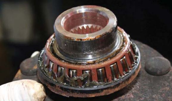
Wheel Bearing Guide Subaru: This tapered roller bearing was damaged by faulty seals that allowed water and dirt to enter the bearing.

The “Achilles Heel” of a wheel bearing is the seal. Although wheel bearings can fail due to damage, improper installation or material imperfection, the most common cause of failure is the seal losing its ability to hold the lubricating grease in and/or dirt and water out.

However, the best seal, applied to the best wheel bearing, cannot be expected to last if not correctly installed. This primer can help you properly service Subaru wheel bearings.

Brake Noise Is It Normal?

Brake Noise Is It Normal?

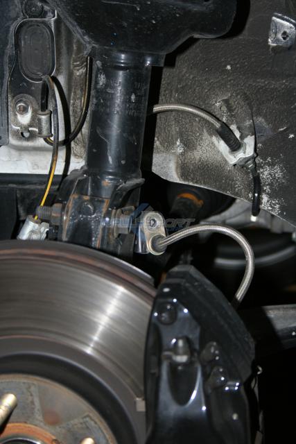
One of the most common concerns that any vehicle owner perceives as a problem is brake noise when stopping the vehicle. The question pops up: “What is considered to be an ‘acceptable’ level of brake noise?”

Brake Noise Is It Normal? One of the most common concerns that any vehicle owner perceives as a problem is brake noise when stopping the vehicle.

The disc brake systems used on vehicles today are designed and developed to meet many different, but very strict requirements. This must be accomplished while providing an optimum level of performance under a wide range of vehicle and environmental operating conditions.
The brake pads selected must be a balanced choice. There is a fine line between a quiet brake pad and one that will provide optimum performance under extreme braking conditions. Consequently, when a change is made in the brake pad formulation (whether it is meant to provide longer pad life, shorter stopping distances, noise reduction or a change in pedal effort), a trade-off must be made in one area or another.

An example of pad formulation change would be the industry’s switch from asbestos to semi-metallic brake linings.

Clutch Pedal Sticking Subaru

Clutch Pedal Sticking Subaru:

If you encounter a clutch pedal not returning completely after being engaged, or if there is a spongy or light clutch pedal feel while shifting, the following repair method should be followed.

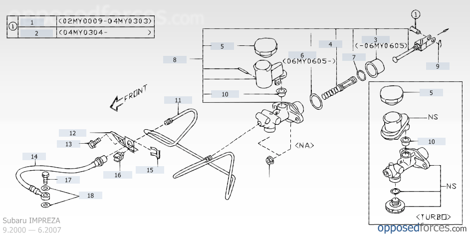
Clutch Pedal Sticking Subaru: This condition may affect certain manual transmission vehicles with a hydraulic clutch system under certain weather conditions.

This condition may affect certain manual transmission vehicles with a hydraulic clutch system under certain weather conditions.The affected manual transmission Subaru models are as follows:

1995-2002 Legacy
1997-2007 2.5L Impreza
1998-2003 Forester

To correct this condition you must replace the parts in the chart that match your vehicle using the following procedures:

Replacement Clutch Parts:

Turbocharger Terms and Definitions

Turbocharger Terms and Definitions:

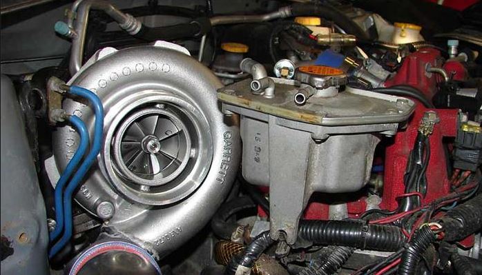
The turbocharger terms and definitions used to describe turbocharger operation can be confusing.

Turbocharger Terms and Definitions:The turbocharger terms and definitions used to describe turbocharger operation can be confusing.
Turbocharger Terms and Definitions: The turbocharger terms and definitions used to describe turbocharger operation can be confusing.

Here are some definitions for common turbocharging terms:

■ Boost Threshold

Boost threshold is the optimum engine speed to produce exhaust gas flow to create positive manifold pressure (boost).

■ Turbo Lag

Turbo lag is the time delay between the point when the throttle is opened and the turbocharger boost reaches operational speed when the engine is running at boost threshold.

Many factors affect turbo lag:

Engine tuning status; the condition of the rotating components; operational condition of the control sensors and components; the presence of any air leaks in the turbocharger system; the control settings; and even the weather.

■ Boost Leak

When air (boost) is leaking within the turbo system or intake, it is referred to as “boost leak.” This may be caused by loose assembly of the components, a bad seal or a cracked component. Under such a condition, the turbocharger may not create enough boost pressure, or reach adequate levels.

■ Boost Spike

A boost spike is an erratic increase in boost pressure, mainly experienced when the vehicle is accelerating through the lower gears and the controller can’t adjust to the changes in engine speeds as quickly as would be ideal.

Boost Pressure Influences

Boost Pressure Influences:

Several factors can influence boost pressure and affect turbocharger efficiency.

Boost Pressure: Several factors can influence boost pressure and affect turbocharger efficiency.

The key factors are:

Ambient Air Temperature and Pressure

As the air temperature rises, the ability of the turbocharger to compress the warmer air decreases. This phenomenon is directly due to the decrease in air density and the physical limitation of the turbocharger.

Even when the air temperature is low, the air density (barometric pressure or boost pressure) may be low. Under these conditions, lower than expected boost pressure may be experienced. The diameter of the exhaust system will vary the pressure differential across the turbine. A larger exhaust allows the turbocharger to rotate faster, which results in higher boost pressure.

Any increase in boost pressure would require “re-mapping” of the ECM programs to accommodate different air flow rates and resultant ignition change requirements. Over-revving of the turbine – trying to supply enough boost – can lead to turbocharger failure, particularly in conjunction with the increase in the pressure differential across the turbine.

Subaru Turbocharger Explained Part 2

Subaru Turbocharger Explained Part 2:

Service Procedures

Here are some service procedures, including steps to properly remove turbocharger components, and tests and inspections you can perform to check component operation.

Subaru Turbocharger Explained: Here are some service procedures, including steps to properly remove turbocharger components, and tests and inspections you can perform to check component operation.

Intercooler Removal

You may need to remove the intercooler to work on other components beneath it. Removal of the intercooler must be performed carefully so that no damage occurs.

1.) Disconnect battery. Remove the two bolts that attach the bypass valve, then the valve.

2.) Remove the bolts from each end of the intercooler and disconnect the crankcase ventilation hoses from the intercooler.

3.) Loosen the clamps at the throttle body and outlet of the turbocharger.

4.) Gently move the intercooler side to side until the tension of the hoses at the turbocharger and throttle body loosen.

5.) Remove the intercooler from the engine compartment and cover the open areas with tape to prevent foreign material from entering, which could cause damage to the engine or turbocharger after re-installation.

Turbocharger Removal

1.) After removing the intercooler, remove the intercooler mounting bracket.

2.) Remove the eight bolts that secure the protective heat shield around the turbo.

3.) Raise the vehicle and disconnect the rear oxygen sensor harness, then remove the front exhaust pipe mounting bolt. Position the pipe so there is some movement.

4.) Lower the vehicle and disconnect the wastegate hose to the vacuum hose leading to the wastegate control solenoid.

5.) Remove the coolant hose from the reservoir that connects to the turbocharger.