Category Archives: Drivetrain

Valve Adjustment DOHC Engine

Valve Adjustment DOHC 2.5 Liter Engine:

The first versions of the 2.5 liter twin cam engines employed non-hydraulic valve actuation. Like the timing belt, the clearance between the engine valves and the shim and bucket valve actuators does not require inspection and/or adjustment until 105,000 miles have elapsed. However, various circumstances may require an adjustment before that milestone is reached.

 Valve Adjustment: Unlike some overhead cam engines that require you to rotate the cam until each cam lobe is facing 180 degrees away from the adjustment shim, Subaru has very specific procedures for adjusting four valves at a time (a pair of intakes and a pair of exhausts).
Valve Adjustment: Unlike some overhead cam engines that require you to rotate the cam until each cam lobe is facing 180 degrees away from the adjustment shim, Subaru has very specific procedures for adjusting four valves at a time (a pair of intakes and a pair of exhausts).

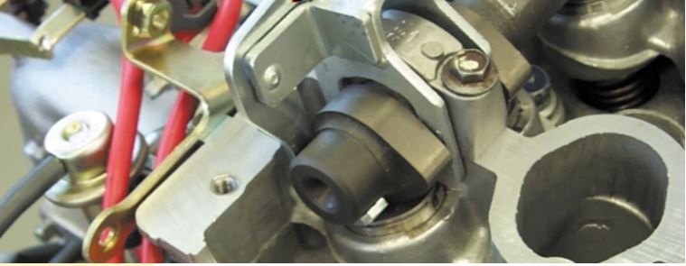
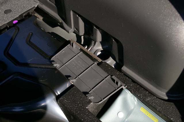
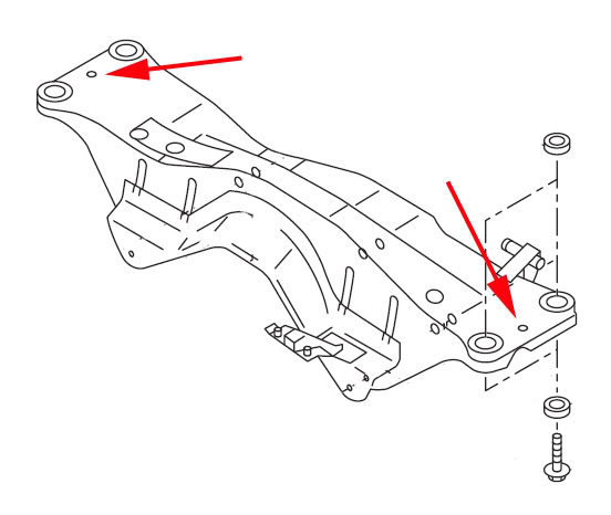
Clearance is tight and there is little room to work between the cylinder heads and the left and right frame rails. A special tool (ST 49818700) is available for depressing the valves and removing the adjusting shims. Without this tool, the job is impossible to accomplish with the engine in the car. Once again, we had the benefit of working on an engine that had already been removed from the car. Before you can adjust the valves, the engine must be cold. Consult the service manual to determine the parts that will need to be moved or removed to make some room to work.

Unlike some overhead cam engines that require you to rotate the cam until each cam lobe is facing 180 degrees away from the adjustment shim, Subaru has very specific procedures for adjusting four valves at a time (a pair of intakes and a pair of exhausts). The pairs of intakes and exhausts are never for the same cylinder, which makes things rather interesting. This system requires you to turn the crankshaft a total of four times to complete the adjustment procedure.

POWER STEERING SYSTEMS ON EARLY SUBARUS PART 3

POWER STEERING SYSTEMS ON EARLY SUBARUS PART 3

Cybrid Power Steering

The Cybrid Power Steering System was standard equipment on the XT6. It’s a computer controlled,
electric motor-driven hydraulic steering system, using a power-assisted rack and pinion assembly similar to the XT. This system provides improved steering feel and more precise power assist over a wider operating range. Fuel consumption is reduced because it requires less horsepower due to the electrically-driven hydraulic pump. The specific system used on the XT6 is quicker than other XT power steering systems, with just 3.2 turns lock-to-lock.

POWER STEERING SYSTEMS ON EARLY SUBARUS PART 3: The Legacy RS used in rallying used the early Subaru power steering system.

Cybrid Steering Components

The Cybrid Power Steering System consists of four major components:

• The Motor and Pump assembly mounted on the front bulkhead (firewall).
• A Steering Sensor located inside the vehicle at the base of the steering column.
• A Signal Controller located in the left rear quarter panel.
• The Power Controller mounted on the front bulkhead (firewall) to the left of the Motor/Pump assembly.

Motor/Pump Assembly

The Motor/Pump assembly is similar to a starter motor, since it has an armature, fields, and brushes which are serviceable. The electric motor drives a pump which is very similar in design to an engine driven pump. This combination replaces the familiar belt driven P/S pump assembly. The Cybrid System requires special hydraulic fluid to retain stable viscosity during cold temperatures.

Heater

The Pump incorporates an electric heater to warm the hydraulic fluid in extremely cold operating conditions, improving the steering performance. A thermistor type switch located on a bracket above the Motor/Pump assembly, senses the underhood (ambient) temperature and sends an input to the Signal Controller.

The Heater operates for approximately five minutes after engine start-up. The Signal Controller grounds the heater relay, which passes battery voltage to the heater. The heater relay is located near the motor/ pump assembly.

Note: The Heater only works when the thermometer signals an extreme cold condition.

Steering Rack Bushings Install on a 08+ STi

Steering Rack Bushings Install on a 08+ STi

This is a step by step guide on installing steering rack bushings (whiteline) on a 08+ WRX/STi. This needs to be done the right way and all the bolts NEED to be torqued with a torque wrench to factory spec for the car to be in a safe operating state.

1.) Remove the under tray. There are 2 12mm bolts towards the front, 1 12mm bolt on the rear, 2 clips on the rear. and 2 plastic pop-out clips on the sides near each wheel well.

2.) After removing the under tray you will need to remove 10 14mm bolts holding the cross member support brace (otherwise known as the jack plate) in place. The bolts that are to be removed are circled in red and yellow.

Note: The bolts circled in yellow are secured by nuts on the topside so you will need the 14mm wench as well. These bolts are torqued down pretty tight if they have never been removed before.

Steering Rack Bushings Install on a 08+ STi: The bolts circled in yellow are secured by nuts on the topside so you will need the 14mm wench as well.

3.) Once the cross member support is removed the steering rack will be exposed as pictured below. Note the location of the 3 bushings denoted by the red arrows.

Steering Rack Bushings Install on a 08+ STi: Note the location of the 3 bushings denoted by the red arrows.

Steering Systems on early Subarus Part 1

Steering Systems on early Subarus Part 1:

Rack And Pinion Steering Mechanism

Subaru steering systems utilize a rack and pinion steering mechanism. As the pinion gear rotates, the rack moves left or right. Rack and pinion steering gives the driver precise control over the wheels. The simple, compact design is easy to service.

Steering Systems on early Subarus Part 1: The Subaru SVX used Subaru's early power steering system.
Steering Systems on early Subarus Part 1: The Subaru SVX used Subaru’s early power steering system.

CGR – VGR Ratios

Two manual steering racks are used in Subaru vehicles: a constant gear ratio (CGR) rack and a variable gear ratio (VGR) rack. The teeth on the CGR rack are equally spaced so the turning effort is equal throughout the turning range. The teeth on the VGR rack are spaced closer together on the ends of the rack than in the middle. The turning effort decreases as the turning angle increases so sharp-radius turns are easier to make.

Legacy and SVX Steering Racks

Several different power steering racks have been installed in Subaru vehicles. The racks used in the L-series, XT, Legacy and SVX vehicles are similar. All have a one-piece gearbox and lack the external air vent distribution tube found on the rack in pre-’85 and carryover vehicles. However, the XT rack differs from the L-series rack in several ways.

The XT rack is made of aluminum and has a different control valve. Different types of hydraulic seals are used in the two racks, and each has its own unique special service tool. The power steering rack in the pre-’85 model year vehicles and the Brat has a two-piece gearbox and an air vent distribution tube. It also has seals, service procedures and special service tools that differ from the other racks.

Rigid Steering Column

Three types of steering columns are used in Subaru vehicles: a rigid steering column, a tilt steering column and the XT and SVX tilt and telescoping steering column. The rigid steering column is found on L-series DL models, the Legacy standard model, and Justy vehicles. The rigid steering shaft does not tilt or pop-up, but is collapsible (a safety feature). The shaft is connected to the gearbox by universal joints.

ABS 5.3 Antilock Brake System for Early Subaru Part 5:

ABS 5.3 Antilock Brake System for Early Subaru Part 5:


ABS 5.3 Antilock Brake System for Early Subaru Part 5: Beginning in approximately December of 1996, a new antilock braking system called ABS 5.3 was installed on Legacy vehicles equipped with ABS.
ABS 5.3 Antilock Brake System for Early Subaru Part 5:
Beginning in approximately December of 1996, a new antilock braking system called ABS 5.3 was installed on Legacy vehicles equipped with ABS.


Beginning in approximately December of 1996, a new antilock braking system called ABS 5.3 was installed on Legacy vehicles equipped with ABS. This system uses a Bosch hydraulic control unit and a Nippon electronic control unit. ABS 5.3 is a four channel control design which can independently control the front wheels and utilize select low control to control the rear wheels (a system which provides the same fluid pressure control for the two rear wheels if either wheel starts to lock up).

Although similar to other Subaru ABS systems, there have been enhancements to component operation and location. Diagnosis has also improved because of the ability of the 5.3 ABS system to communicate with the Select Monitor. The hydraulic control unit or HCU is located under the hood on the right side of the engine compartment. The size of the HCU has decreased by approximately a third from that of the ABS-2E system, used on previous model year vehicles.

The HCU controls brake fluid flow by utilizing eight solenoid valves. There is an inlet solenoid valve and an outlet solenoid valve for each wheel. Mechanically, the inlet solenoid valve is open during normal braking, and the outlet solenoid valve is closed. The HCU also contains a motor and pump assembly, which operates only while ABS is actively controlling the brake fluid flow–preventing a wheel lock.

Beginning in approximately December of 1996, a new antilock braking system called ABS 5.3 was installed on Legacy vehicles equipped with ABS.
ABS 5.3: Beginning in approximately December of 1996, a new antilock braking system called ABS 5.3 was installed on Legacy vehicles equipped with ABS.

Externally the HCU of the ABS 5.3 has a relay box attached. This allows troubleshooting of the valve and motor relay area to be kept separate from the troubleshooting of the solenoid valves and pump motor. There are four modes of operation for the ABS 5.3 system. They are normal, pressure-drop, pressure-hold and pressure-increase. When wheel lockup is sensed, Mode Two, Mode Three and Mode Four may be activated. They are described as follows:

Axle general maintenance:

Axle general maintenance:

Front stub axle seal replacements require special precautions. The seals are pressed into a side bearing retainer, which must be removed to replace a leaking seal. The side bearing retainers also control front differential side bearing preload, as well as ring and pinion backlash.

When replacing a stub axle seal, mark the position of the side bearing retainer before un-threading the retainer. Remove only one side bearing retainer at a time, or you’ll risk disturbing the differential adjustments. If you’ve marked the position before removal, the correctly installed position of the side bearing retainer will be obvious, as you will be unable to turn the retainer another complete turn.

2008-Subaru-Impreza-WRX-Hatchback-Front-Axle-Parts-Assembly
Axle general maintenance: A driveaxle for a 2008 Subaru Impreza WRX.

The driveaxles on some Subaru vehicles are pressed into the wheel hub with a light press fit. Blasting the axle out of the hub with an air chisel, center punch or other implement of destruction invites damage to the wheel bearings. All of the force brought to bear by these methods finds its way to the wheel bearings, possibly damaging their races or balls. Special tools are available for removing and installing  press-fit driveaxles. Ignoring these cautions invites a comeback for noisy wheel bearings shortly after your CV axle repair work.

Rear strut brace install on Subaru WRX/STi 08+:

Rear strut brace install on Subaru WRX/STi 08+:

This is a step by step guide on how to install a rear strut brace in a 2008+ Subaru WRX/STi. Installing a rear strut brace on a 2008+ WRX/STi is more much more involved than installing a front brace. The chassis is significantly different than the new-age 02-07 Subaru Impreza. The need to cut clearances into the floor for the left and right brackets increases the difficulty for this install.

1.) Only work on one strut tower at a time. Only loosen one set of nuts at a time, and do not put the car up on lifts, jacks, or anything else that lifts the tires off the ground. All of these precautions are to minimize changes to the alignment while working on the installation.

2.) Loosen the left and right hinges on the rear strut brace using the 17mm socket and the 8mm allen head wrench. You want to be able to move the brace around as you attach each side bracket to the car’s strut towers.

3.) Remove the hatch floor and set it aside.

Rear strut brace install on Subaru WRX/STi 08+: Remove the rear floor.

4.) Remove the left and right panels from the wheel covering so that you’ll have access to the tops of the strut towers. Working your finger tips under the edge of the panel and carefully working my way around the edges while pulling away from the wheel cover worked best without requiring any special tools. It also helped avoid scratching the plastic.

Rear strut brace install on Subaru WRX/STi 08+: Remove these panels both both sides with your hands. If you can't do that gently use a screwdriver to remove.
Rear strut brace install on Subaru WRX/STi 08+: Remove these panels both both sides with your hands. If you can’t do that gently use a screwdriver to remove.

Subframe Lockbolt install for Subaru WRX/STi

Subframe Lockbolt install for Subaru WRX/STi:

This is a step by step guide on installing a subframe lockbolt kit into the rear subframe of your 02-07 Subaru Impreza WRX/STi.

Subframe Lockbolt install for Subaru WRX/STi: Where these two red arrows point to are where the lockout bolts will be installed.

The rear subframe is isolated by rubber bushings which allow some movement relative the WRX/STi chassis. This movement can be the source of a rubbery feeling during launch and hard cornering. Enough rear subframe movement may alter the rear toe settings and affect handling during advanced driving. Depending on which lockbolt brand you use the adapter portion may not sit flush to the subframe surface, this is part of the design and is OK.

The lockbolt is not designed to stop vertical movement of the rear subframe. It is meant to limit movement in the horizontal plane. PB Blaster will soften the factory undercoating spray thus making a mess. WD-40 is not as aggressive so less black mess is made.