Category Archives: TMIC

Wastegate and Boost Creep FAQ

Wastegate and Boost Creep FAQ

What is Boost Creep?

Boost creep is a situation where your wastegate port is not large enough to allow the exhaust gas to bypass the turbo. What happens is the exhaust gas will choke the wastegate port preventing further gas flow through the port. Then, the exhaust gas has to take the path of least resistance which is through the turbine of the turbo. This will spool the turbo ‘uncontrolled’ beyond your normal controlled max boost level.

Wastegate and Boost Creep FAQ: A stock Subaru turbo.

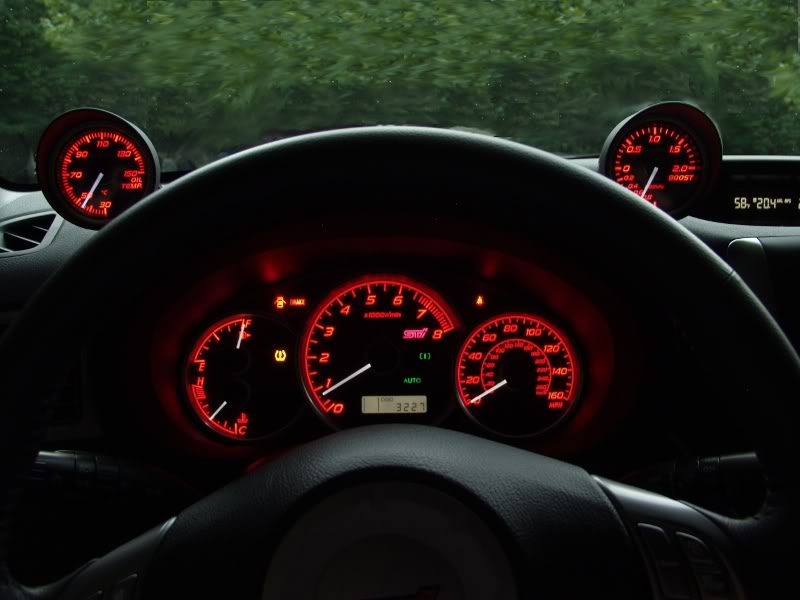
The turbo will be spooling past wastegate spring rate pressure even though the wastegate is fully open thus it is uncontrolled. The best way to check for boost creep is to connect the turbo outlet port directly to the wastegate actuator port and go for a drive. In 4th gear you should normally get a stable boost level of about 0.5 BAR, if you have boost creep the boost will hit 0.5 BAR and will continue to rise with rpm until you either back off or hit overboost fuel cut.

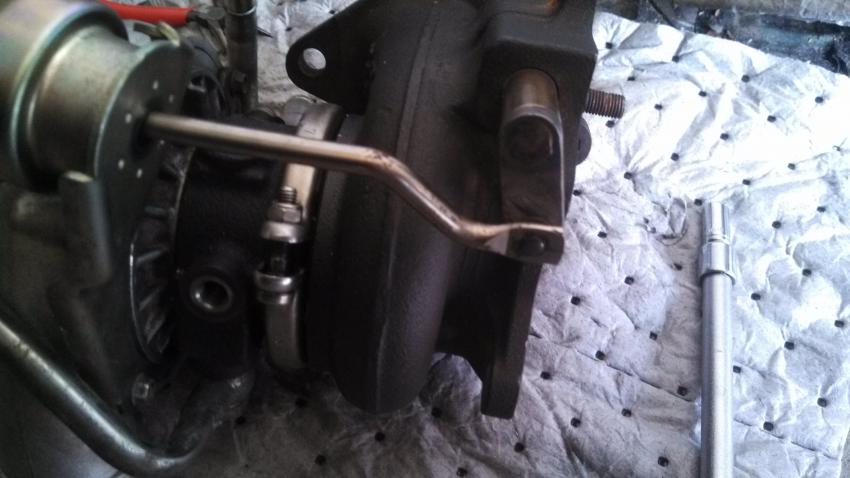
Boost creep should only be present on a turbo that has very little restriction. For example a fully de-catted and high flow induction. It’s been found that the fast spooling IHI VF35 is very prone to boost creep. The cure is to remove the turbo and enlarge the wastegate port. Then, fit a stronger actuator 0.75 BAR the reason for this is because you have made the wastegate port larger. The effective size of the wastegate plate acting against the exhaust gas flow is larger which allows the exhaust gas excert more force on the wastegate plate.

This in effect weakens the effectiveness of the actuator. Before the increase in size of your wastegate port the actuator would open at 0.5 BAR, after the increase the actuator would open earlier at 0.3–0.4 BAR. After these changes are made to the turbo either a boost controller or a remap (to adjust solenoid duty cycle) should be sought to control the boost to a safe level.

Boost control systems on a Turbo Subaru:

Boost control system on a Turbo Subaru:

This guide covers most  boost related issues including a short introduction on how your boost systems work. This information is based on the Classic Impreza’s, but will cover the newer WRX/STi cars to a certain extent.

Safe boost levels:

When modding your car without mapping (full de-cat and high flow induction etc) you increase the efficiency of your turbo which could result in engine damage due to lean running at high rpm / max boost. To prevent damage always try and keep your boost level as close to standard as possible until your car is mapped for the increase in boost pressure.

TLDR: Don’t screw with your boost levels until you get the car tuned by someone who knows what they are doing. Otherwise you’ll probably end up with a blown up Subaru.

Boost Issues:

Is the boost control system connected correctly:

JDM Automatic Intercooler STi Switch Install:

JDM Automatic Intercooler STi Switch Install:

Here is the step by step guide to installing the JDM Automatic Intercooler STi switch. For those of you wondering the advantage of upgrading to the JDM automatic intercooler switch is that it essentially works as a on/off switch for the STi intercooler sprayer. So there is no more constant pushing of the sprayer button. Push the button once to turn it on, and again to turn it off. However, it will empty out your intercooler sprayer tank very quickly if you keep it on.

Here is the switch we are going to be installed:

JDM Automatic Intercooler Switch: The JDM intercooler switch that you will be installing.

1.) Pop out the fuse box panel. The fuse box panel is located underneath and to the left of the steering wheel.

2.) Use your fingers to depress the tab on the button of the button to pop it out.

JDM Automatic Intercooler Switch: The USDM stock STi switch that you will be removing.

3.) Pull the switch out of the dash.

4.) Depress the tab on the back of the plug to remove the switch.

JDM Automatic Intercooler Switch: USDM STi intercooler switch removed. Get ready to install the JDM switch now.

Strut Tower Brace front install WRX/STi

Strut tower front brace install WRX/STi:

This strut tower brace guide should work on both 04 and 05’s just fine (mine is an 05). I’m not sure about the 06s’ since they relocated the AC line and it looks like Whiteline makes the only strut bar that will work on an 06. A little bit of modification with the 06+ model cars might be necessary. These are also specific to the JDM Spec-C Titanium Strut Bar but should work as a general guide for any strut bar on an STi.

1.) Remove alarm horn bar from passenger strut tower bolts which are 12mm. Disconnect the horn and put it aside for now. We’ll screw the horn into the side of the strut tower once we’ve installed the strut bar.

Strut tower brace: Removing the alarm horn bracket. Some models did not come with the alarm horn option so you do not need to do this.

2.)Lower the AC line bracket down a screw. This is the AC Bracket you need to unscrew (use a philips head screw driver or 10mm ratchet). You’ll need to remove the bolt that connects the AC line to the bracket and also the bracket where it connects to the firewall. Remount the bracket down a screw by mounting the upper hole where the bottom screw hole on the firewall is. The bracket is the copper colored metal piece.

Strut Tower Brace: Remove the copper bracket off of it’s mount on the firewall.

3.) Install Strut Bar.

First remove the bolts holding the struts to the strut walls. Bolts are 12mm. They should come off pretty easily since they are only torqued down to 14.5ft-lbs.

I found it was easiest to unscrew the strut bar into 3 pieces, the 2 parts that connect to the strut tower and then the actual bar itself (bolts/screws are 12mm). I put the round strut tower parts on first and loosely bolted them down. Then I placed the strut bar on top and loosely screwed down the strut bar to the strut tower connection pieces.

Strut tower brace: Passenger side strut bar end installed.
Strut Tower Brace: Driver’s side strut bar end installed.

Pitch Stop Install on Subaru WRX/STi

Pitch Stop Mount Install on Subaru WRX/STi:

This is a step by step guide on how to install an aftermarket Pitch Stop Mount to your 02-07 Subaru WRX or STi.

Pitch Stop Mount: In the foreground a oem plastic pitch mount and in the background a Perrin Performance pitch stop mount.

1.) Locate and remove the three 10 mm Gold colored bolts that secure the black vacuum lines to the bottom of the intercooler. You will need a shallow socket as it gets tight around the BOV. Careful not to drop them into the engine bay, it will be a PITA to find and retrieve them.

2.) Locate and remove the two 12 mm bolts that secure the recirculating BOV to the bottom of the intercooler. Again be careful not to drop these into the engine bay as it’s a jungle down there and it will be a PITA to retrieve them.

3.) Locate and remove the two 12 mm bolts that secure the intercooler to the engine. These are located one on each side of the intercooler.

4.) Now the intercooler is only held in place by the rubber intake hoses with the clamps. The one that is on top, from the intercooler to the throttle body/intake manifold is easier so do them first. Using the Flat head screw driver or an 8 mm socket loosen the clamps holding the intake piping to the Intake manifold and intercooler. And leave it for now.

5.) This is a little tough to do, but its not impossible. You should be able to do it even if you have large hands. Using the flat head or 8 mm socket, loosen the clamp that holds the intake tube coming from the cold side of the turbo to the intercooler. This is located underneath the intercooler.

O2 Sensor replacement on 02-07 Subaru WRX/STi:

O2 Sensor replacement on 02-07 Subaru WRX/STi:

This is a guide to replace your front 02 sensor in your 02-07 Subaru WRX/STi. This guide will go step by step through the process.

Denso 234-9120 Oxygen Sensor (Air and Fuel Ratio Sensor)

O2 sensor location in the exhaust manifold.

1.) The first thing you need to do is place the jack under your car. I chose to use the pinch weld under the passenger’s door area. Next you will want to remove the wheel from the car so you will have better access to the O2 sensor. I did this by using a 19mm socket with an extension.

2.) Upon removing the wheel, you should notice a small plastic flap with a few plastic retaining screws holding it in place. I have circled them in red in the picture below.

3.) You are going to want to remove these using flat head and phillips head screw drivers. Take care in making sure you do your best to not strip them out. If you do, you will end up having to either pry them out or pull them out with a set of pliers. If you need to replace any of these, you can usually find them at any autoparts store.

4.) Once you have all of the plastic screws pulled out, remove the plastic cover.

5.) If you pull the remaining plastic cover to the right, you will be able to see the O2 sensor. You can opt to remove the larger of the plastic fender well shields, but I did not see much point in doing so as it would not really yield much more room for access.

6.) With the O2 sensor exposed, you will want to spray it with some lubricant and my preferred lubricant is PB Blaster. With that now soaking in a bit, you are now going to want to go and pop your hood to gain access to the plug end of the sensor.

7.) Looking at your engine bay, you will want to move to the left side (passenger side). Underneath this cover are two connections, the top one is for your front O2 sensor. Go ahead and disconnect that plug.

Boost Gauge Install on Subaru STi/WRX 08-13:

Boost Gauge Install on Subaru STi/WRX 08-13:

This is a guide on installing a boost gauge in a 2010 STi.

Boost Gauge: A installed boost gauge in a GR STi.

Boost Gauge: INTERIOR WIRING AND GAUGE INSTALLATION

1.) Pull off the lower dash cover. It just has clips holding it on.

2.) These are the only two screws that hold the lower dash to rest of the dash. Remove these and the rest of the lower dash can be pulled off.

3.) Lower dash pulled away from the upper, left of the steering wheel.

4.) Lower dash pulled away from the upper, right side of the steering wheel.

5.) There are 4 clips holding the instrument hood to the dash. The entire hood pulls off as one whole unit, but the hard part is getting a good grip. To get better finger placement, I pulled the top of the inner part of the hood away, which revealed a little lip that I could use to pull the hood off. Caution: Do not pull heavily on the inner piece because it is bolted to the rest of the hood at the bottom and could break if you pull on it too hard. Just pull on the top part of the instrument hood itself. Also be careful not to lose the 4 yellow clips that hold the hood to the dash. They come out easily and can get lost.

6.) There are two screws for the instrument cluster. One is circled in the pic and the other is to its left.

7.) Pop the plug off the cluster on the right side.

8.) I ran the wires for the boost gauge through the upper middle hole above the gauge cluster.

9.) Tap into the purple wire on the dimmer switch for headlight power. This wire is only powered when the headlights or parking lights are turned on.

10.) Close-up of where I spliced into the purple wire. For the boost gauge, the ORANGE wire splices into this purple wire. The wire is black in my picture because I used black wire to extend the wires coming out of the back of the gauge.

11.) For ACC power, use the brown and white striped wire on the top connector above the fuse box. This wire is powered when the key is in the “ACC” position only. With the boost gauge, you connect BOTH the RED and WHITE wires to this wire.

The green and white striped wire on the same connector is on all the time, meaning it is powered even when the car is off. I found that out the hard way. (Do not use that wire.)

Banjo Bolt (Union) removal/install on a Subaru WRX STi

Banjo Bolt (Union) removal and install on a Subaru WRX STi:

This is Banjo Bolt step by step guide on the removal and installation of a Banjo bolt and new copper washers for a Subaru WRX/STi or any other turbocharged Subaru.The Banjo bolt is the one with a filter screen that others have indicated should be cleaned or replaced periodically. Subaru calls it a “Union screw (with protrusion).”
Tools needed:
12 mm socket – for intercooler bracket bolt
14 mm deep-well socket – for up-pipe bracket nut and bolt
10 mm socket or wrench – for stock turbo heat shield bolt
17 mm ratcheting wrench – for Banjo bolt
10 inch or longer extension – to reach up-pipe bracket bolts

Parts needed:
Union screw/Banjo Bolt (If replacing which I highly suggest you do.) – Subaru part # 14445AA090

Subaru 14445AA090 Oil Filter Bolt

OR

Genuine Subaru Turbo Banjo Bolt with Screen – 14445AA090a
Copper washers (2) – Subaru part # 803912040
Subaru 803912040 Banjo Washer


Removal and re-install takes about one hour.

Start by removing any heat shields that are in the way. I have the SPT heat shield that comes off by removing the 12 mm intercooler support bolt.
(See pic “Engine bay area”). I also have the stock turbo heat shield installed. I didn’t take it off, but there will be a little more room to work if you do. A 10 mm socket is needed to remove the stock heat shield bolts.

The next page will describe the removal and re-installation process of the Banjo Bolt and copper washers.