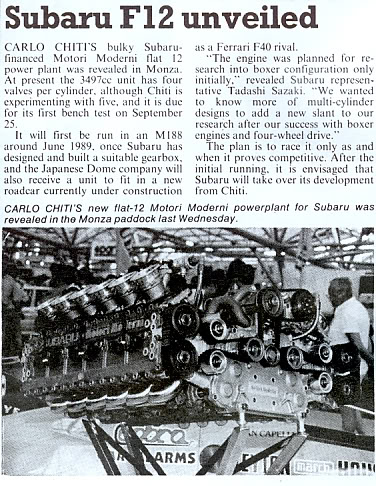
In 1990 Subaru took over the Coloni Formula One team, acquiring a 51% ownership stake, paying off the team’s debts, and supplying a new, unique engine. The engine was a flat-12 called the “MM” series, which in fact was penned by Carlo Chiti.
Formula 1 Subaru Flat-12: In late 1988, the Japanese commissioned Chiti to design a new Formula One engine with a “flat” layout, as used in their road cars.
Chiti’s Motori Moderni company at Novara had supplied V6 turbo engines for the Minardi Formula One team from 1985 to 1987, and in 1988 Chiti had penned a naturally aspirated V12 engine that attracted Subaru. In late 1988, the Japanese commissioned Chiti to design a new Formula One engine with a “flat” layout, as used in their road cars.
The engine was completed in the summer of 1989, and was tested in a Minardi M188 chassis; due to a severe lack of power, Minardi lost interest. After a few months of searching, Subaru found the Coloni team. Eventually, the Subaru Coloni team was founded with Enzo Coloni staying on board as the man for operational business.
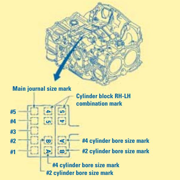
The picture below of this paragraph shows the location of piston size and main journal size information on all Subaru engines. As the figure illustrates, it is possible to have more than one piston size in the same engine.
Subaru Engine Block Piston Size Identifier: The picture on the bottom shows the location of piston size and main journal size information on all Subaru engines. As the figure illustrates, it is possible to have more than one piston size in the same engine.
The importance of checking electrical ground connections during any electrical troubleshooting cannot be over stressed. For example, a poor electrical ground at the radiator support or fender (depending on the affected Subaru model) may cause any or all of the following problems:
• The door ajar indicator light dims when the brake pedal is applied.
• There is a loss of communication with the Automatic Transmission side of the New Select Monitor when the vehicle is put into gear.
• The engine starts running poorly after driving only a few feet.
• There is a loss of communication with the Anti-lock Brake side of the New Select Monitor when the brake pedal is applied.
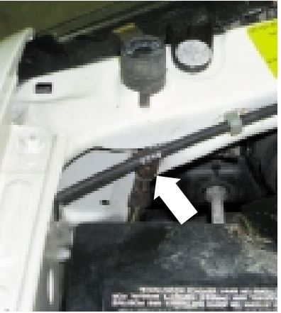
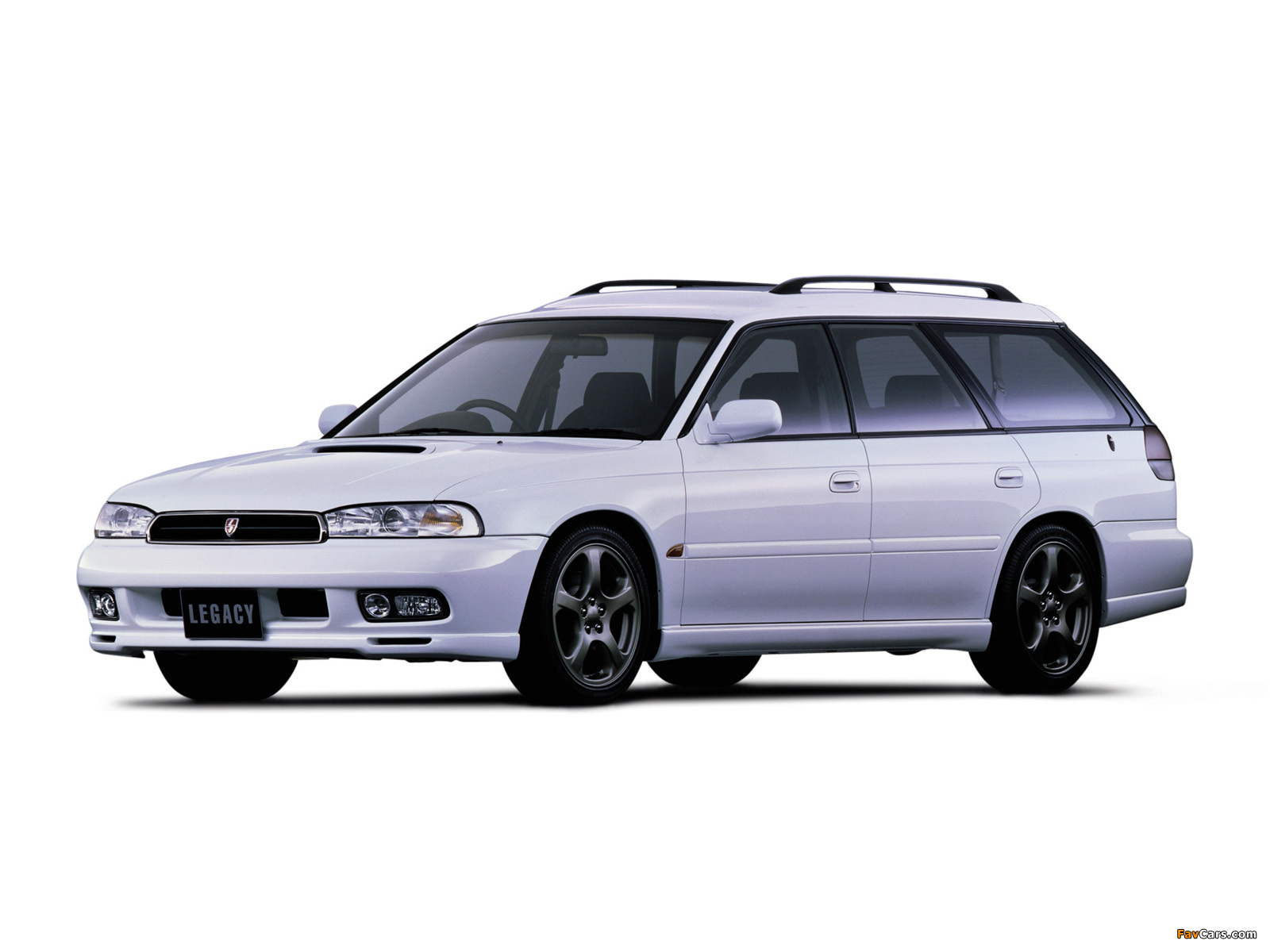
Vehicles that have been involved in accidents should be inspected especially closely. In the example below, a Subaru Legacy had been involved in a front end collision.
During reassembly of the vehicle, the electrical ground wire behind the left front headlight that fastens to the radiator support had not been reinstalled (refer to photo). This electrical ground is attached to the left front fender on Subaru Impreza and Forester models. After reinstalling this ground wire, all of the affected systems returned to proper working order.
Electrical Grounding System inspection: The importance of checking ground connections during any electrical troubleshooting cannot be over stressed.
Subaru vehicles are more reliable than ever before. To assure their continued reliability, a schedule of inspection and maintenance (I & M) services is prescribed by Subaru of America for every Subaru vehicle sold. A copy of this schedule can be found in the Warranty and Maintenance Booklet located in the vehicle glove compartment.
Maintenance Inspections for Subaru: Subaru vehicles are more reliable than ever before. To assure their continued reliability, a schedule of inspection and maintenance (I & M) services is prescribed by Subaru of America for every Subaru vehicle sold.
Subaru vehicle maintenance inspections services are divided into recommended intervals beginning with three months or 3000 miles (whichever comes first). Each additional level in the maintenance schedule (7,500/15,000/ 30,000 miles) adds more maintenance and inspection steps to the process. The 15,000 (15 month) and 30,000 mile (30 month) services are ‘major’ services, and include the most comprehensive range of component checks, part replacements and adjustments.
If you are already familiar with Subaru vehicles, you may have developed a routine when performing a vehicle safety maintenance inspections. Following a set routine allows you to start at one end of the vehicle and end up at the other end, having performed all of the necessary safety inspection steps along the way.
Repetition of the safety inspection may also allow you to commit the steps to memory, but a checklist can be a helpful addition that leaves nothing to chance (or memory). Checking items off the checklist provides a written record that can be shared with the customer and retained for your service records as well.
Recommended steps in a Subaru Safety Maintenance Inspections are also spelled out in the owner’s Warranty and Maintenance Booklet. Some of the steps overlap services performed during the scheduled maintenance program. It could be argued that any scheduled maintenance should always include a Safety Inspection. Most of the Safety Maintenance Inspection steps are based on common sense, but it’s surprising how frequently these simple suggestions are ignored.
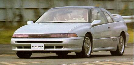
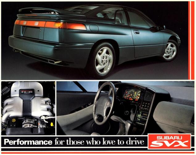
SVX Power Steering Systems on Early Subarus Part 4:
There are two model-specific systems available on SVX vehicles:
SVX Power Steering Systems on Early Subarus Part 4: The engine speed sensitive, or conventional belt driven hydraulic pump and pinion type steering system is standard equipment on the SVX.
• The engine speed sensitive, or conventional belt driven hydraulic pump and pinion type steering system is standard equipment on the SVX.
• An SVX equipped with the SVX Touring Package uses an optional vehicle speed-sensitive system. This system provides normal power assist at low vehicle speeds for reduced driver steering effort, and reduced steering assist at increased vehicle speeds for increased road feel and improved engine operating efficiency. Both systems have many similarities with the Legacy system.
Both systems share many similarities to existing Subaru steering systems. Both use a belt driven power steering pump, although the pump housings are different in appearance.
Rack
A conventional power assisted rack with the standard Subaru lines and hoses is used by the standard system.
Oil Cooler
An oil cooler pipe has been added to both SVX systems. It is located in front of the radiator on the return side of the system.
Rubber Coupler
A steering shaft rubber coupler is used by both SVX systems to reduce road noise and vibration.
SVX Power Steering Pressure Switch
A power steering pressure switch is located on the outlet side of the pump. The switch monitors increased engine load during idle speed steering. The switch provides an input to the MPFI ECU, which prevents stalling by raising the engine idle speed. There is not an additional trouble code for the MPFI ECU.
Subaru’s power steering system contains a pump, hydraulic line, and a gearbox (rack). The hydraulic pump is a vane-type pump driven by the engine. It provides pressurized fluid for the system.
Power Steering Systems On Early Subarus Part 2: Subaru’s power steering system contains a pump, hydraulic line, and a gearbox (rack). The hydraulic pump is a vane-type pump driven by the engine. It provides pressurized fluid for the system.
Oil Pump Operation
The pump has two internal valves: a flow control valve and a relief valve. The flow control valve regulates the volume of power steering fluid delivered to the rack. During high engine rpm, the pressure in the pump overcomes the flow control valve spring. The control valve slides back to close off an oil passage to the rack and to open an oil return port to the pump inlet. This reduces the power assist to the rack during high speeds, improving the steering wheel feel and response.
Subaru steering systems utilize a rack and pinion steering mechanism. As the pinion gear rotates, the rack moves left or right. Rack and pinion steering gives the driver precise control over the wheels. The simple, compact design is easy to service.
Steering Systems on early Subarus Part 1: The Subaru SVX used Subaru’s early power steering system.
CGR – VGR Ratios
Two manual steering racks are used in Subaru vehicles: a constant gear ratio (CGR) rack and a variable gear ratio (VGR) rack. The teeth on the CGR rack are equally spaced so the turning effort is equal throughout the turning range. The teeth on the VGR rack are spaced closer together on the ends of the rack than in the middle. The turning effort decreases as the turning angle increases so sharp-radius turns are easier to make.
Several different power steering racks have been installed in Subaru vehicles. The racks used in the L-series, XT, Legacy and SVX vehicles are similar. All have a one-piece gearbox and lack the external air vent distribution tube found on the rack in pre-’85 and carryover vehicles. However, the XT rack differs from the L-series rack in several ways.
The XT rack is made of aluminum and has a different control valve. Different types of hydraulic seals are used in the two racks, and each has its own unique special service tool. The power steering rack in the pre-’85 model year vehicles and the Brat has a two-piece gearbox and an air vent distribution tube. It also has seals, service procedures and special service tools that differ from the other racks.
Rigid Steering Column
Three types of steering columns are used in Subaru vehicles: a rigid steering column, a tilt steering column and the XT and SVX tilt and telescoping steering column. The rigid steering column is found on L-series DL models, the Legacy standard model, and Justy vehicles. The rigid steering shaft does not tilt or pop-up, but is collapsible (a safety feature). The shaft is connected to the gearbox by universal joints.
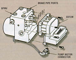
ABS 5.3 Antilock Brake System for Early Subaru Part 5:
ABS 5.3 Antilock Brake System for Early Subaru Part 5: Beginning in approximately December of 1996, a new antilock braking system called ABS 5.3 was installed on Legacy vehicles equipped with ABS.
Beginning in approximately December of 1996, a new antilock braking system called ABS 5.3 was installed on Legacy vehicles equipped with ABS. This system uses a Bosch hydraulic control unit and a Nippon electronic control unit. ABS 5.3 is a four channel control design which can independently control the front wheels and utilize select low control to control the rear wheels (a system which provides the same fluid pressure control for the two rear wheels if either wheel starts to lock up).
Although similar to other Subaru ABS systems, there have been enhancements to component operation and location. Diagnosis has also improved because of the ability of the 5.3 ABS system to communicate with the Select Monitor. The hydraulic control unit or HCU is located under the hood on the right side of the engine compartment. The size of the HCU has decreased by approximately a third from that of the ABS-2E system, used on previous model year vehicles.
The HCU controls brake fluid flow by utilizing eight solenoid valves. There is an inlet solenoid valve and an outlet solenoid valve for each wheel. Mechanically, the inlet solenoid valve is open during normal braking, and the outlet solenoid valve is closed. The HCU also contains a motor and pump assembly, which operates only while ABS is actively controlling the brake fluid flow–preventing a wheel lock.
ABS 5.3: Beginning in approximately December of 1996, a new antilock braking system called ABS 5.3 was installed on Legacy vehicles equipped with ABS.
Externally the HCU of the ABS 5.3 has a relay box attached. This allows troubleshooting of the valve and motor relay area to be kept separate from the troubleshooting of the solenoid valves and pump motor. There are four modes of operation for the ABS 5.3 system. They are normal, pressure-drop, pressure-hold and pressure-increase. When wheel lockup is sensed, Mode Two, Mode Three and Mode Four may be activated. They are described as follows:
We use cookies on our website to give you the most relevant experience by remembering your preferences and repeat visits. By clicking “Accept”, you consent to the use of ALL the cookies.
This website uses cookies to improve your experience while you navigate through the website. Out of these, the cookies that are categorized as necessary are stored on your browser as they are essential for the working of basic functionalities of the website. We also use third-party cookies that help us analyze and understand how you use this website. These cookies will be stored in your browser only with your consent. You also have the option to opt-out of these cookies. But opting out of some of these cookies may affect your browsing experience.
Necessary cookies are absolutely essential for the website to function properly. These cookies ensure basic functionalities and security features of the website, anonymously.
Cookie
Duration
Description
cookielawinfo-checkbox-analytics
11 months
This cookie is set by GDPR Cookie Consent plugin. The cookie is used to store the user consent for the cookies in the category "Analytics".
cookielawinfo-checkbox-functional
11 months
The cookie is set by GDPR cookie consent to record the user consent for the cookies in the category "Functional".
cookielawinfo-checkbox-necessary
11 months
This cookie is set by GDPR Cookie Consent plugin. The cookies is used to store the user consent for the cookies in the category "Necessary".
cookielawinfo-checkbox-others
11 months
This cookie is set by GDPR Cookie Consent plugin. The cookie is used to store the user consent for the cookies in the category "Other.
cookielawinfo-checkbox-performance
11 months
This cookie is set by GDPR Cookie Consent plugin. The cookie is used to store the user consent for the cookies in the category "Performance".
viewed_cookie_policy
11 months
The cookie is set by the GDPR Cookie Consent plugin and is used to store whether or not user has consented to the use of cookies. It does not store any personal data.
Functional cookies help to perform certain functionalities like sharing the content of the website on social media platforms, collect feedbacks, and other third-party features.
Performance cookies are used to understand and analyze the key performance indexes of the website which helps in delivering a better user experience for the visitors.
Analytical cookies are used to understand how visitors interact with the website. These cookies help provide information on metrics the number of visitors, bounce rate, traffic source, etc.
Advertisement cookies are used to provide visitors with relevant ads and marketing campaigns. These cookies track visitors across websites and collect information to provide customized ads.