Category Archives: Suspension

Maintenance: Subaru Periodic Maintenance Part 4:

Maintenance: Subaru Periodic Maintenance Part 4:

Steering and Suspension:

Steering and suspension parts are a lot like the brake system components. Their proper operation is vitally important to the safety of the driver and his passengers, but it is very difficult to determine how long it will be before any of these components will require attention. That’s why an inspection of all steering and suspension components is required at 15 month/15,000 mile intervals. Changes to these systems may be too gradual for the driver to even notice, leaving it to you to ferret out and correct any wear or damage that has taken place.

Maintenance:Subaru Periodic Maintenance Part 4: Regular checks of the steering and suspension is important.

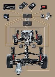
We won’t cover all of the steering and suspension checks here. There’s too much variation between different Subaru models to do an adequate job. What you’re looking for is anything that reduces the original precision of the steering and suspension systems. Perhaps the steering has a little too much play in it or the shocks and struts don’t handle the bumps in the road as well as they did when new. Specific tests for the Subaru model you’re working on can be found in the service manual.

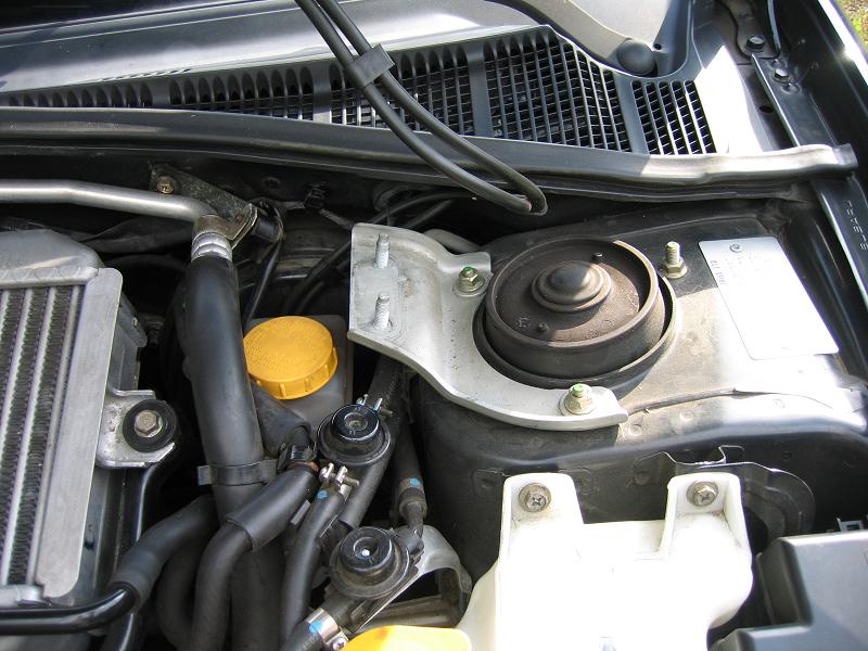
Check the power steering system for dampness or other signs of fluid leakage. The power steering pump reservoir is a good place to start. If the reservoir is low, the fluid has probably leaked out, as it has no place else to go. Approved fluids for the power steering system include Dexron II, IIE or III.


GENUINE OEM SUBARU ATF-HP P/S FLUID QUART BOTTLE

Rear strut brace install on Subaru WRX/STi 08+:

Rear strut brace install on Subaru WRX/STi 08+:

This is a step by step guide on how to install a rear strut brace in a 2008+ Subaru WRX/STi. Installing a rear strut brace on a 2008+ WRX/STi is more much more involved than installing a front brace. The chassis is significantly different than the new-age 02-07 Subaru Impreza. The need to cut clearances into the floor for the left and right brackets increases the difficulty for this install.

1.) Only work on one strut tower at a time. Only loosen one set of nuts at a time, and do not put the car up on lifts, jacks, or anything else that lifts the tires off the ground. All of these precautions are to minimize changes to the alignment while working on the installation.

2.) Loosen the left and right hinges on the rear strut brace using the 17mm socket and the 8mm allen head wrench. You want to be able to move the brace around as you attach each side bracket to the car’s strut towers.

3.) Remove the hatch floor and set it aside.

Rear strut brace install on Subaru WRX/STi 08+: Remove the rear floor.

4.) Remove the left and right panels from the wheel covering so that you’ll have access to the tops of the strut towers. Working your finger tips under the edge of the panel and carefully working my way around the edges while pulling away from the wheel cover worked best without requiring any special tools. It also helped avoid scratching the plastic.

Rear strut brace install on Subaru WRX/STi 08+: Remove these panels both both sides with your hands. If you can’t do that gently use a screwdriver to remove.

Subframe Lockbolt install for Subaru WRX/STi

Subframe Lockbolt install for Subaru WRX/STi:

This is a step by step guide on installing a subframe lockbolt kit into the rear subframe of your 02-07 Subaru Impreza WRX/STi.

Subframe Lockbolt install for Subaru WRX/STi: Where these two red arrows point to are where the lockout bolts will be installed.

The rear subframe is isolated by rubber bushings which allow some movement relative the WRX/STi chassis. This movement can be the source of a rubbery feeling during launch and hard cornering. Enough rear subframe movement may alter the rear toe settings and affect handling during advanced driving. Depending on which lockbolt brand you use the adapter portion may not sit flush to the subframe surface, this is part of the design and is OK.

The lockbolt is not designed to stop vertical movement of the rear subframe. It is meant to limit movement in the horizontal plane. PB Blaster will soften the factory undercoating spray thus making a mess. WD-40 is not as aggressive so less black mess is made.

Antilock Brake System For Early Subaru Part 2:

Antilock Brake System for Early Subarus:

ABS Service And Brake Bleeding Procedures:

Antilock Brake System for Early Subarus: The first Subaru rally car the Legacy RS relied upon the bousch/nippon ABS units to perform on the WRC circuit.

Always check the fluid level of the master cylinder and bleed the wheel cylinders following the procedure listed in the service manual. When the HCU has been removed and/or replaced, the fluid must be drained. Replace the cone screws with bleed screws and attach a hose to drain fluid to a container.

Antilock: ABS Service And Brake Bleeding Procedures: A early Subaru Nippon ABS unit ECU.

Use extreme care when performing this procedure to prevent damage to the internal components of the HCU. Do not apply AV signal for more than 5 seconds for each application. If no AV signal is received, it is not necessary to close bleed screw between brake pedal applications.

Antilock Brake System Notes and Cautions:

The ECU on early Subaru ABS systems can only display one trouble code–the lowest numbered code. Correct the fault indicated by the trouble code and recheck ECU for another code. Repeat the self-diagnostic procedure listed above, and the next highest code will be displayed. Refer to the appropriate model year service manual for the trouble codes and corrective actions. While the ABS ECU is in the fault mode, the ABS will go to fail-safe and remain passive under all braking conditions. The brake system will function as a conventional power-assisted system without ABS.

Antilock Brake System for Early Subaru Part 1:

Antilock Brake System for Early Subarus:

A variety of antilock brake system (ABS) have been installed in Subaru vehicles since the first systems were installed in the 1990 Legacy.  In the sections that follow, we’ll give you a brief overview of each system and explain proper diagnostic techniques.

Antilock Brake System for Early Subarus: A Subaru SVX ABS system.

Antilock Brake System for Early Subarus:

Early Subaru Antilock Brake Systems:

The original Subaru Legacy Antilock Brake System (ABS) was licensed by Bosch and manufactured by Nippon ABS, Ltd. The system electronically controls brake fluid pressure supplied to the brake system. This control helps to prevent “wheel lockup” during braking on slippery surfaces and emergency situations. The system includes a fail-safe feature, which indicates a malfunction by illuminating the warning lamp. The system is then returned to a conventional power brake system. The four channel system provides accurate individual wheelspeed control and improves the directional stability of the vehicle during braking.

Antilock Brake System (ABS) Components

• Tone wheels (4)

• Speed sensors (4)

• Electronic control unit (ECU)

• Hydraulic control unit (HCU)

• G sensor (manual transmission models)

• Warning lamp

A tone wheel is attached to each wheel hub and rotates at the same speed as the hub. The magnetic speed sensor is mounted in the axle housing. The notched tone wheel acts as a reluctor which modulates the magnetic field of the speed sensor. The tone wheels are individually replaceable.

The speed sensor provides an alternating voltage signal to the ECU. The alternating voltage and frequency corresponds to wheelspeed.

ALK (Anti-Lift Kit) install on 02-07 Subaru WRX/STi:

ALK (Anti-Lift Kit)install on 02-07 Subaru WRX/STi:

This is a step by step guide on how to install a Anti-Lift Kit (ALK) onto a 02-07 WRX/STi. These ALK (Anti-Lift Kits) are designed to be used with the STi’s aluminum control arms.

1.) First unpackage your Anti-Lift Kit (ALK) it’ll look something like this.

Anti-Lift Kit (ALK): This is all the components you’ll get with this kit.

2.)  Get your tools ready and mount the car up properly on jack stands to prevent the car falling down on you. Get as much clearance as you can as you’ll need a lot of room to work with.

Anti-Lift Kit (ALK): Get the front of your STi up on jack stands.

3.) Make sure you have a decent breaker bar. I’ve destroyed a breaker bar doing this before. Do not use a 3/8 inch drive. Use a 1/2 inch drive so you don’t break a breaker bar and a socket.

Sway bar (front) and endlinks install on GD STi:

Front sway bar and endlinks install on 02-07 STi:

This is a step by step guide in installing a front sway bar with aftermarket endlinks on a 04-07 Subaru STi.

1.) Get the car in the air and be sure to secure the car. I used jack stands in the cutouts on the side of the car’s lower frame. It may be easier to use ramps since you will need to tighten the sway bar mounting bolts when the suspension is “loaded,” that is when the full weight of the car is on the wheels/tires.

2.) Remove the front lower cover (splash guard). There are five bolts that require a 12 mm socket, three in the front and two toward the rear. There are two pop fasteners on each side as well. These can be removed by using a small flat bladed screwdriver to pop up the center round plastic piece about a quarter of an inch then pulling/wriggling out the entire fastener.

3.) Remove the jack plate. There are four bolts in the center area to remove and two nuts on each side.

Front sway bar and endlinks: Remove splash guard and skid plate.

4.) The sub-frame is an odd looking, approximately C shaped, bracket under the front part of the car. The opening of the C is toward the rear of the car. It helps to remove this to make it easier to get to the bolts that hold the sway bar onto the frame.

The sub-frame has five bolts on each leg of the C and two toward the front of the car. The two rearmost bolts require a 14mm socket, the other three on each side require a 17mm socket and the two on the front require a 12mm socket. Start by removing a plastic cover on each side that is held in place by two pop fasteners.

Front sway bar and endlinks install on 02-07 STi: The sub-frame is an odd looking, approximately C shaped, bracket under the front part of the car. The opening of the C is toward the rear of the car. It helps to remove this to make it easier to get to the bolts that hold the sway bar onto the frame.

5.) Remove another pop fastener on each side of the sub-frame.

Strut Tower Brace front install WRX/STi

Strut tower front brace install WRX/STi:

This strut tower brace guide should work on both 04 and 05’s just fine (mine is an 05). I’m not sure about the 06s’ since they relocated the AC line and it looks like Whiteline makes the only strut bar that will work on an 06. A little bit of modification with the 06+ model cars might be necessary. These are also specific to the JDM Spec-C Titanium Strut Bar but should work as a general guide for any strut bar on an STi.

1.) Remove alarm horn bar from passenger strut tower bolts which are 12mm. Disconnect the horn and put it aside for now. We’ll screw the horn into the side of the strut tower once we’ve installed the strut bar.

Strut tower brace: Removing the alarm horn bracket. Some models did not come with the alarm horn option so you do not need to do this.

2.)Lower the AC line bracket down a screw. This is the AC Bracket you need to unscrew (use a philips head screw driver or 10mm ratchet). You’ll need to remove the bolt that connects the AC line to the bracket and also the bracket where it connects to the firewall. Remount the bracket down a screw by mounting the upper hole where the bottom screw hole on the firewall is. The bracket is the copper colored metal piece.

Strut Tower Brace: Remove the copper bracket off of it’s mount on the firewall.

3.) Install Strut Bar.

First remove the bolts holding the struts to the strut walls. Bolts are 12mm. They should come off pretty easily since they are only torqued down to 14.5ft-lbs.

I found it was easiest to unscrew the strut bar into 3 pieces, the 2 parts that connect to the strut tower and then the actual bar itself (bolts/screws are 12mm). I put the round strut tower parts on first and loosely bolted them down. Then I placed the strut bar on top and loosely screwed down the strut bar to the strut tower connection pieces.

Strut tower brace: Passenger side strut bar end installed.
Strut Tower Brace: Driver’s side strut bar end installed.