
Turbocharger: How to choose a Turbocharger for your Turbo Subaru:
Twin turbos on Subarus are rarely seen. Though there are no official numbers, one would guess that the amount in the United States could be counted on one hand. The reason for the rarity is due to cost, customization, and tuning that is involved with this type of set-up. This is definitely something one would want to leave to a professional. It requires enormous amounts of fabrication, careful planning, and time to execute in a reliable fashion. Aside from the mounting, tuning is also critical, as the turbos tend to fight each other to see which one can push the most air into the engine. This is especially true at higher boost levels and is something that takes a real professional to mechanically isolate and/or electronically tune.
Few Subaru modifications get the heart pumping as much as aftermarket turbos. This article will get down to the brass tacks to allow you to make an educated choice in what turbo specifications are and how to match them to your wishes.
The first step is to learn some terminology as it applies to turbos:
CHRA Center Housing Rotating Assembly. This is the internal part of the turbo from the bearing area between the two halves of the turbo shell to the main shaft and both blades.
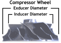
Compressor Inducer smaller diameter portion of the compressor blade.
Compressor Exducer larger diameter portion of the compressor blade.
Turbine Inducer larger diameter portion of the exhaust blade.
Turbine Exducer smaller diameter portion of the exhaust blade.
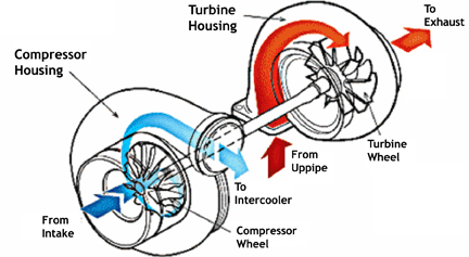
Turbine is the complete wheel inside the turbine housing. Its purpose is to spin via exhaust gas, which in turn spins the compressor wheel.
Compressor complete wheel inside the compressor housing. Its purpose is to compress the intake charge on its way to the intercooler.
Compressor map X/Y plot of the compressor’s efficiency range. After mathematical calculations based on your vehicle and desires, you end up with a plot that is used to determine turbo suitability.
Trim relationship of the inducer and exducer of a given wheel. Compressor trim = (inducer²/exducer²) ×100. Turbine trim = (exducer²/inducer²) ×100. All measurements are in millimeters. You will end up with a trim of say .64 which will be expressed as a 64 trim wheel. In almost every case, advertised trim ratios reflect those of the compressor wheel vice the turbine wheel. In a perfect world, the higher trim numbers will produce more power and more lag while lower trim numbers will spool faster but produce less power. This is not always the case though as A/R plays a role in the manipulation of the airflow as well.
A/R Area/Radius Ratio. One way to envision the concept of the A/R ratio is to think of the way the turbine housing wraps around the turbo. Imagine it as cornucopia that wraps around the turbine. The A portion is the small end and its shape and size effects the force which exhaust gases hit the blades. The R portion is the distance from the center of the section area in the turbine housing at the 12 o’clock position to the center of the turbine shaft; the size, shape, and distance of travel all affect the ultimate turbine velocity. The A/R is then the ratio between the volume of the compressor where it discharges to the turbine to the distance to between the turbine shaft to the center of the 12 o’clock position. This is a summary of the definition as provided by Corky Bell.
Interestingly enough, the definition from Garrett is slightly different. The A portion is exactly the same as the below documented MHI THA. The R portion is the distance from the center of the section area in the turbine housing at the 12 o’clock position to the center of the A portion.
As to which definition is most correct, that’s anyone’s guess, but the definition is not so important as the concept of the ratios. The A/R can be applied to both the compressor and turbine housings. In most cases though, the compressor A/R has little effect on turbo performance, so it is not given. As to turbine A/R, the smaller number A/R will generate quicker spool, but less top end power and the higher A/R number will generate more power at the cost of slower spool. This holds true when comparing different A/R figures of the same sized turbine housing.
MHI Turbine Housing Area (THA) is the newly created term for the “A/R” of MHI turbos. While their measurement area differs slightly from the traditional A/R, the end result is similar whereas the smaller numbers spool faster with less top end and the larger numbers spool slower with more top end. This measurement is technically the area of the housing at the 12 o’clock position.