Category Archives: USDM

Wheel Alignment For Subarus:

Wheel Alignment For Subaru:

Wheel arch height (vehicle ride height) as well as front and rear wheel alignment should be inspected at 30 month/30,000 mile intervals. Winter driving and its attendant chuckholes may shorten that maintenance interval for some drivers

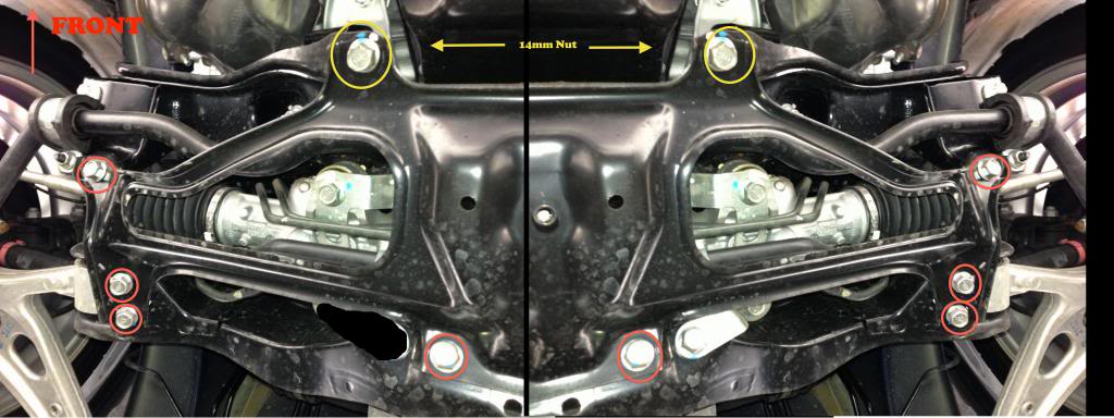
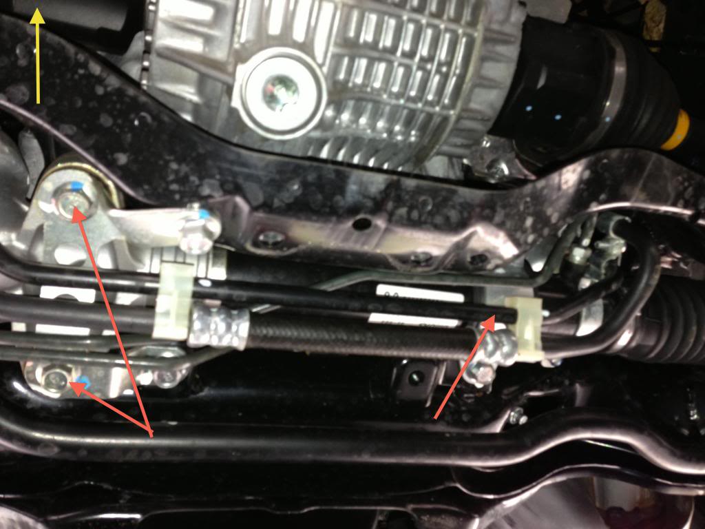
While inspecting wheel alignment, also check for obvious signs of damage to suspension components, tightness of bolts and nuts and the condition of other under car components.

Check, adjust and/or measure wheel alignment in accordance with the following procedures:

1.) Wheel arch height (front and rear)
2.) Camber (front and rear)
3.) Caster (front)
4.) Front toe-in
5.) Rear toe-in
6.) Thrust angle (rear)
7.) Wheel steering angle

1. Wheel Arch Height

1.) Adjust the tire pressures to specifications.
2.) Set the vehicle under “curb weight” conditions (empty luggage compartment, install spare tire, jack, service tools, and top off fuel tank).
3.) Set steering wheel in a wheel-forward position.
4.) Suspend a thread from the wheel arch (point “A” in figure above) to determine a point directly above the center of the spindle.

Subaru Wheel Alignment: Measure the distance between the measuring point and the center of the spindle.

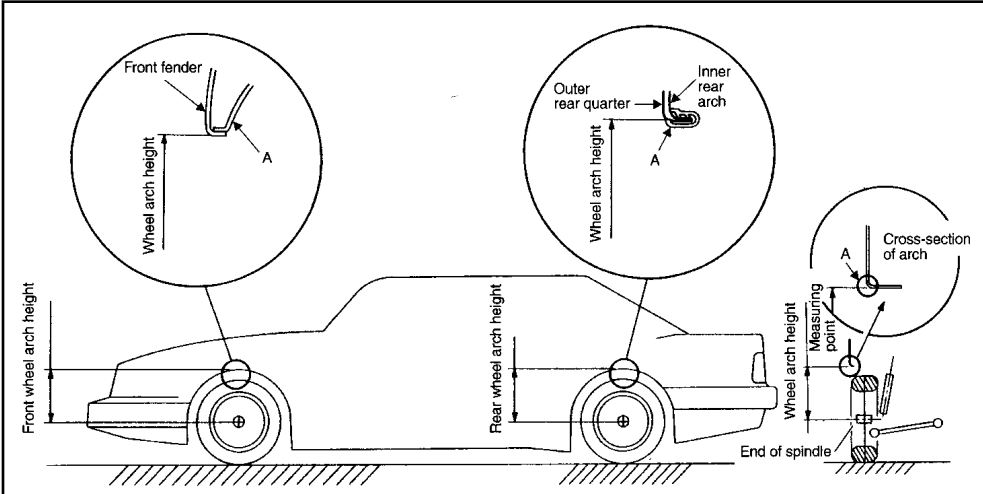
5.) Measure the distance between the measuring point and the center of the spindle.
6.) Consult the service manual for Wheel Arch Height specifications.

Valve Adjustment DOHC Engine Part 2

Valve Adjustment Tool and
Adjustment Procedures:

As we mentioned, it takes a special tool to work within the limited clearance area between the cylinder heads and the frame rails. The ST 498187 is a three part tool. One part wraps around the cam lobes, a second touches the outer edges of two shim buckets, and a third eccentric bolt exerts the necessary pressure to push a pair of shim buckets away from the cam lobe to make shim removal and replacement possible.

The tool installed in the three steps:

• Wrap the first half of the tool (part A) around the lobes.
• Attach the second half (part B) to part A by sliding its pins through the slotted holes in part A.
• Install the eccentric bolt (part C) into the hole in part A.

Valve Adjustment Tool and Adjustment Procedures: As we mentioned, it takes a special tool to work within the limited clearance area between the cylinder heads and the frame rails.

The eccentric bolt forces parts A and B away from one another. Because part A can’t move (it’s wedged against the cam lobes), the only thing that can move is part B. Part B moves by forcing the shim buckets downward, away from the camshaft.

Valve Adjustment DOHC Engine

Valve Adjustment DOHC 2.5 Liter Engine:

The first versions of the 2.5 liter twin cam engines employed non-hydraulic valve actuation. Like the timing belt, the clearance between the engine valves and the shim and bucket valve actuators does not require inspection and/or adjustment until 105,000 miles have elapsed. However, various circumstances may require an adjustment before that milestone is reached.

 Valve Adjustment: Unlike some overhead cam engines that require you to rotate the cam until each cam lobe is facing 180 degrees away from the adjustment shim, Subaru has very specific procedures for adjusting four valves at a time (a pair of intakes and a pair of exhausts).
Valve Adjustment: Unlike some overhead cam engines that require you to rotate the cam until each cam lobe is facing 180 degrees away from the adjustment shim, Subaru has very specific procedures for adjusting four valves at a time (a pair of intakes and a pair of exhausts).

Clearance is tight and there is little room to work between the cylinder heads and the left and right frame rails. A special tool (ST 49818700) is available for depressing the valves and removing the adjusting shims. Without this tool, the job is impossible to accomplish with the engine in the car. Once again, we had the benefit of working on an engine that had already been removed from the car. Before you can adjust the valves, the engine must be cold. Consult the service manual to determine the parts that will need to be moved or removed to make some room to work.

Unlike some overhead cam engines that require you to rotate the cam until each cam lobe is facing 180 degrees away from the adjustment shim, Subaru has very specific procedures for adjusting four valves at a time (a pair of intakes and a pair of exhausts). The pairs of intakes and exhausts are never for the same cylinder, which makes things rather interesting. This system requires you to turn the crankshaft a total of four times to complete the adjustment procedure.

Limited Spoiler 07 STi install:

Limited Spoiler 07 STi install:

This is a step by step guide in installing the Limited Spoiler from a 07 STi.

Here is the limited spoiler, already painted to match the lid:

The part number is actually E7210FE900 and the kit cost $221 shipped at the time of purchase, but prices may have changed.

Limited Spoiler 07 STi install: Here is the spoiler already painted and ready to install.

1.)From the factory this fitting is already installed in the center of the spoiler, if you bought it unpainted, remove this BEFORE you get your spoiler painted. It just makes it easier. I simply cut the nipple off so that nothing is protruding from the bottom of the spoiler. You can also use the nipple and cut a hole in your trunk.

Limited Spoiler 07 STi install: Limited Spoiler 07 STi install: If you bought it unpainted, remove this BEFORE you get your spoiler painted.
Limited Spoiler 07 STi install: If you bought it unpainted, remove this BEFORE you get your spoiler painted.

2.) The 3M tape you want to use looks like this, I picked it up at the local auto parts/auto body shop. You can see the part number in the picture. It costs around $15 and you will have enough for two or more installations.

The 3M tape you want to use looks like this, I picked it up at the local auto parts/auto body shop. You can see the part number in the picture.

You can buy the 3M Tape here:


3M(TM) Automotive Acrylic Plus Attachment Tape 06384, Black, 1/2 In X 5 Yds, 45 mil [PRICE is per ROLL]

Steering Rack Bushings Install on a 08+ STi

Steering Rack Bushings Install on a 08+ STi

This is a step by step guide on installing steering rack bushings (whiteline) on a 08+ WRX/STi. This needs to be done the right way and all the bolts NEED to be torqued with a torque wrench to factory spec for the car to be in a safe operating state.

1.) Remove the under tray. There are 2 12mm bolts towards the front, 1 12mm bolt on the rear, 2 clips on the rear. and 2 plastic pop-out clips on the sides near each wheel well.

2.) After removing the under tray you will need to remove 10 14mm bolts holding the cross member support brace (otherwise known as the jack plate) in place. The bolts that are to be removed are circled in red and yellow.

Note: The bolts circled in yellow are secured by nuts on the topside so you will need the 14mm wench as well. These bolts are torqued down pretty tight if they have never been removed before.

Steering Rack Bushings Install on a 08+ STi: The bolts circled in yellow are secured by nuts on the topside so you will need the 14mm wench as well.

3.) Once the cross member support is removed the steering rack will be exposed as pictured below. Note the location of the 3 bushings denoted by the red arrows.

Steering Rack Bushings Install on a 08+ STi: Note the location of the 3 bushings denoted by the red arrows.

Nice Price or Crackpipe? Subaru Convertible Addition

Custom convertible Subaru Impreza
6 speed
Convertible
Rear view camera
Leather interior
Fully loaded
Located in Amesbury, MA
Call, text or email for details or to set up time for test drive
$32,500

This car is in excellent condition, it’s super fast and fun to drive! My husband LOVES this car unfortunately for him with the arrival of our new baby he’s going to be driving a minivan! #FamilyLife

A Subaru Impreza convertible. Nothing quite says I've ruined my car more than this.
A Subaru Impreza convertible. Nothing quite says I’ve ruined my car more than this.

Someone needs to get this car out of it’s misery. Also do not ever get in a crash with this thing, because bad things will happen.

Link

Power Steering Systems On Early Subarus Part 2

Power Steering Systems On Early Subarus Part 2:

Power Steering Rack System

Subaru’s power steering system contains a pump, hydraulic line, and a gearbox (rack). The hydraulic pump is a vane-type pump driven by the engine. It provides pressurized fluid for the system.

Power Steering Systems On Early Subarus Part 2: Subaru’s power steering system contains a pump, hydraulic line, and a gearbox (rack). The hydraulic pump is a vane-type pump driven by the engine. It provides pressurized fluid for the system.

Oil Pump Operation

The pump has two internal valves: a flow control valve and a relief valve. The flow control valve regulates the volume of power steering fluid delivered to the rack. During high engine rpm, the pressure in the pump overcomes the flow control valve spring. The control valve slides back to close off an oil passage to the rack and to open an oil return port to the pump inlet. This reduces the power assist to the rack during high speeds, improving the steering wheel feel and response.

Steering Systems on early Subarus Part 1

Steering Systems on early Subarus Part 1:

Rack And Pinion Steering Mechanism

Subaru steering systems utilize a rack and pinion steering mechanism. As the pinion gear rotates, the rack moves left or right. Rack and pinion steering gives the driver precise control over the wheels. The simple, compact design is easy to service.

Steering Systems on early Subarus Part 1: The Subaru SVX used Subaru's early power steering system.
Steering Systems on early Subarus Part 1: The Subaru SVX used Subaru’s early power steering system.

CGR – VGR Ratios

Two manual steering racks are used in Subaru vehicles: a constant gear ratio (CGR) rack and a variable gear ratio (VGR) rack. The teeth on the CGR rack are equally spaced so the turning effort is equal throughout the turning range. The teeth on the VGR rack are spaced closer together on the ends of the rack than in the middle. The turning effort decreases as the turning angle increases so sharp-radius turns are easier to make.

Legacy and SVX Steering Racks

Several different power steering racks have been installed in Subaru vehicles. The racks used in the L-series, XT, Legacy and SVX vehicles are similar. All have a one-piece gearbox and lack the external air vent distribution tube found on the rack in pre-’85 and carryover vehicles. However, the XT rack differs from the L-series rack in several ways.

The XT rack is made of aluminum and has a different control valve. Different types of hydraulic seals are used in the two racks, and each has its own unique special service tool. The power steering rack in the pre-’85 model year vehicles and the Brat has a two-piece gearbox and an air vent distribution tube. It also has seals, service procedures and special service tools that differ from the other racks.

Rigid Steering Column

Three types of steering columns are used in Subaru vehicles: a rigid steering column, a tilt steering column and the XT and SVX tilt and telescoping steering column. The rigid steering column is found on L-series DL models, the Legacy standard model, and Justy vehicles. The rigid steering shaft does not tilt or pop-up, but is collapsible (a safety feature). The shaft is connected to the gearbox by universal joints.