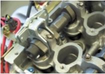
As we mentioned, it takes a special tool to work within the limited clearance area between the cylinder heads and the frame rails. The ST 498187 is a three part tool. One part wraps around the cam lobes, a second touches the outer edges of two shim buckets, and a third eccentric bolt exerts the necessary pressure to push a pair of shim buckets away from the cam lobe to make shim removal and replacement possible.
The tool installed in the three steps:
• Wrap the first half of the tool (part A) around the lobes.
• Attach the second half (part B) to part A by sliding its pins through the slotted holes in part A.
• Install the eccentric bolt (part C) into the hole in part A.
Valve Adjustment Tool and Adjustment Procedures: As we mentioned, it takes a special tool to work within the limited clearance area between the cylinder heads and the frame rails.
The eccentric bolt forces parts A and B away from one another. Because part A can’t move (it’s wedged against the cam lobes), the only thing that can move is part B. Part B moves by forcing the shim buckets downward, away from the camshaft.
This is a step by step guide in installing the Limited Spoiler from a 07 STi.
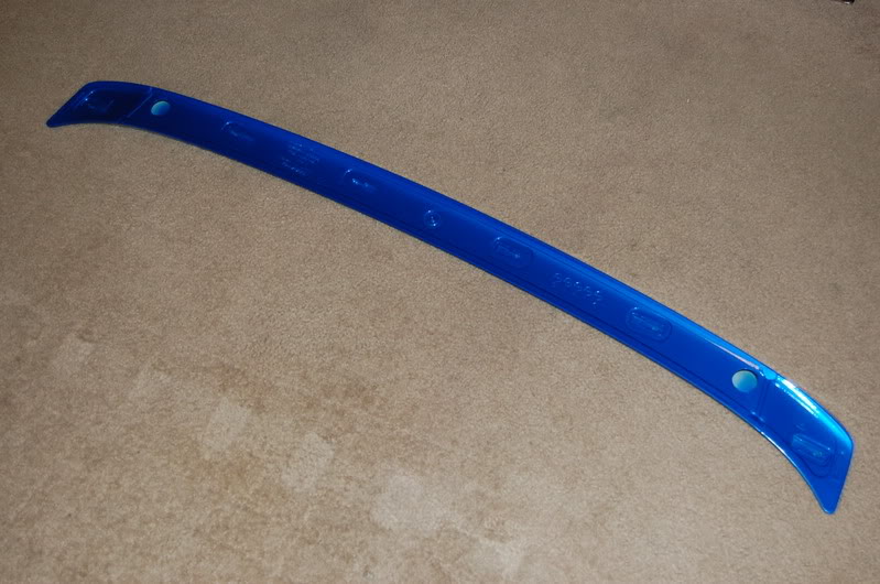
Here is the limited spoiler, already painted to match the lid:
The part number is actually E7210FE900 and the kit cost $221 shipped at the time of purchase, but prices may have changed.
Limited Spoiler 07 STi install: Here is the spoiler already painted and ready to install.
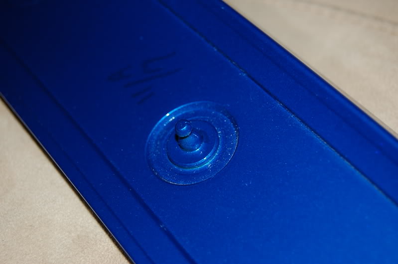
1.)From the factory this fitting is already installed in the center of the spoiler, if you bought it unpainted, remove this BEFORE you get your spoiler painted. It just makes it easier. I simply cut the nipple off so that nothing is protruding from the bottom of the spoiler. You can also use the nipple and cut a hole in your trunk.
Limited Spoiler 07 STi install: If you bought it unpainted, remove this BEFORE you get your spoiler painted.
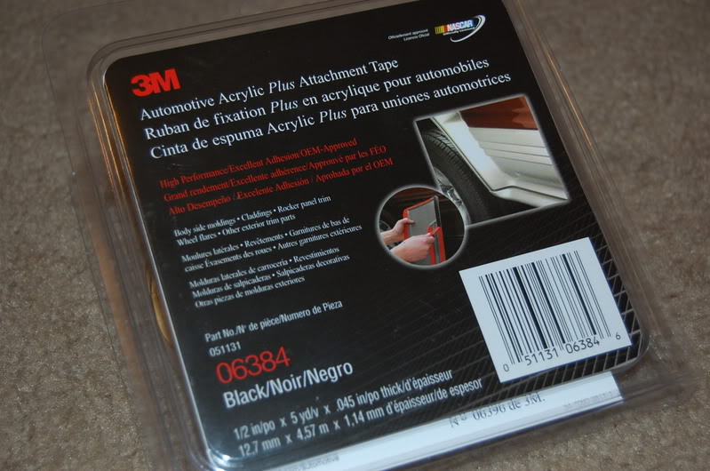
2.) The 3M tape you want to use looks like this, I picked it up at the local auto parts/auto body shop. You can see the part number in the picture. It costs around $15 and you will have enough for two or more installations.
The 3M tape you want to use looks like this, I picked it up at the local auto parts/auto body shop. You can see the part number in the picture.
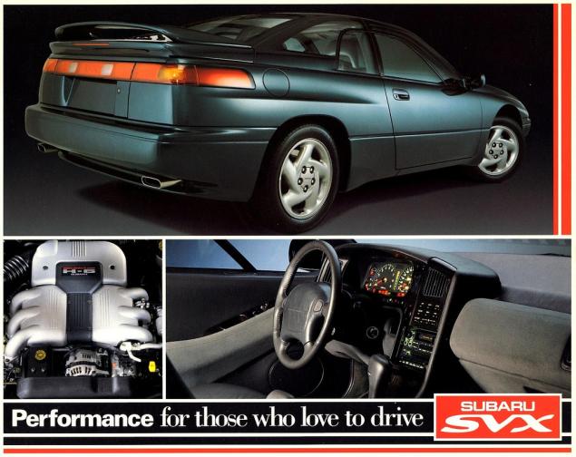
SVX Power Steering Systems on Early Subarus Part 4:
There are two model-specific systems available on SVX vehicles:
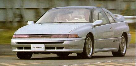
SVX Power Steering Systems on Early Subarus Part 4: The engine speed sensitive, or conventional belt driven hydraulic pump and pinion type steering system is standard equipment on the SVX.
• The engine speed sensitive, or conventional belt driven hydraulic pump and pinion type steering system is standard equipment on the SVX.
• An SVX equipped with the SVX Touring Package uses an optional vehicle speed-sensitive system. This system provides normal power assist at low vehicle speeds for reduced driver steering effort, and reduced steering assist at increased vehicle speeds for increased road feel and improved engine operating efficiency. Both systems have many similarities with the Legacy system.
Both systems share many similarities to existing Subaru steering systems. Both use a belt driven power steering pump, although the pump housings are different in appearance.
Rack
A conventional power assisted rack with the standard Subaru lines and hoses is used by the standard system.
Oil Cooler
An oil cooler pipe has been added to both SVX systems. It is located in front of the radiator on the return side of the system.
Rubber Coupler
A steering shaft rubber coupler is used by both SVX systems to reduce road noise and vibration.
SVX Power Steering Pressure Switch
A power steering pressure switch is located on the outlet side of the pump. The switch monitors increased engine load during idle speed steering. The switch provides an input to the MPFI ECU, which prevents stalling by raising the engine idle speed. There is not an additional trouble code for the MPFI ECU.
The Cybrid Power Steering System was standard equipment on the XT6. It’s a computer controlled,
electric motor-driven hydraulic steering system, using a power-assisted rack and pinion assembly similar to the XT. This system provides improved steering feel and more precise power assist over a wider operating range. Fuel consumption is reduced because it requires less horsepower due to the electrically-driven hydraulic pump. The specific system used on the XT6 is quicker than other XT power steering systems, with just 3.2 turns lock-to-lock.
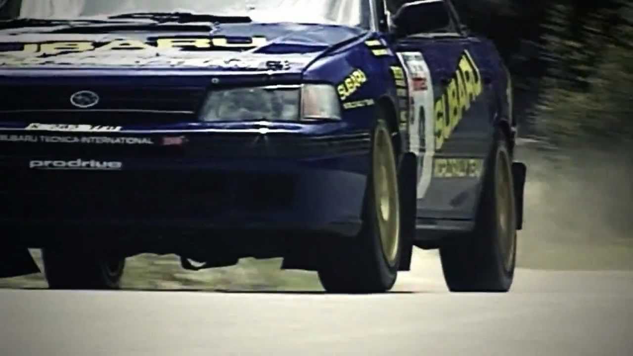
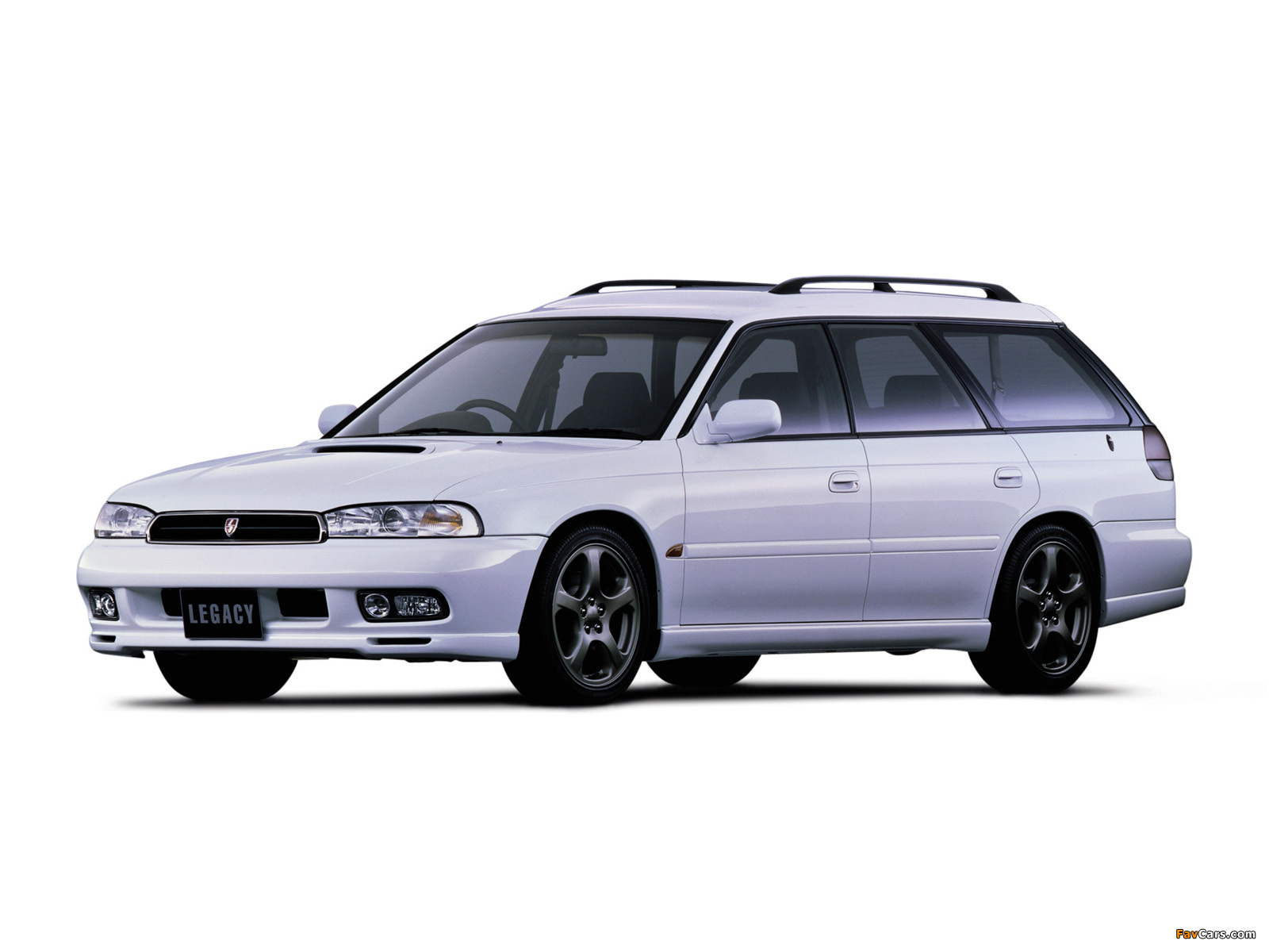
POWER STEERING SYSTEMS ON EARLY SUBARUS PART 3: The Legacy RS used in rallying used the early Subaru power steering system.
Cybrid Steering Components
The Cybrid Power Steering System consists of four major components:
• The Motor and Pump assembly mounted on the front bulkhead (firewall).
• A Steering Sensor located inside the vehicle at the base of the steering column.
• A Signal Controller located in the left rear quarter panel.
• The Power Controller mounted on the front bulkhead (firewall) to the left of the Motor/Pump assembly.
Motor/Pump Assembly
The Motor/Pump assembly is similar to a starter motor, since it has an armature, fields, and brushes which are serviceable. The electric motor drives a pump which is very similar in design to an engine driven pump. This combination replaces the familiar belt driven P/S pump assembly. The Cybrid System requires special hydraulic fluid to retain stable viscosity during cold temperatures.
Heater
The Pump incorporates an electric heater to warm the hydraulic fluid in extremely cold operating conditions, improving the steering performance. A thermistor type switch located on a bracket above the Motor/Pump assembly, senses the underhood (ambient) temperature and sends an input to the Signal Controller.
The Heater operates for approximately five minutes after engine start-up. The Signal Controller grounds the heater relay, which passes battery voltage to the heater. The heater relay is located near the motor/ pump assembly.
Note: The Heater only works when the thermometer signals an extreme cold condition.
This is a step by step guide on installing steering rack bushings (whiteline) on a 08+ WRX/STi. This needs to be done the right way and all the bolts NEED to be torqued with a torque wrench to factory spec for the car to be in a safe operating state.
1.) Remove the under tray. There are 2 12mm bolts towards the front, 1 12mm bolt on the rear, 2 clips on the rear. and 2 plastic pop-out clips on the sides near each wheel well.
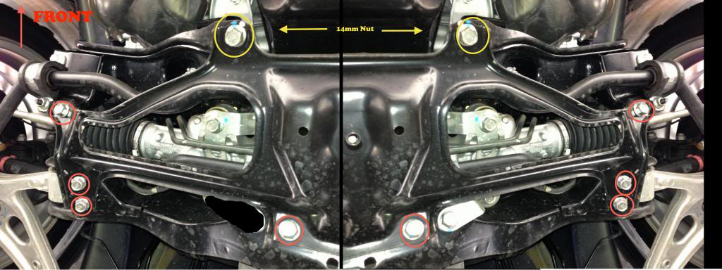
2.) After removing the under tray you will need to remove 10 14mm bolts holding the cross member support brace (otherwise known as the jack plate) in place. The bolts that are to be removed are circled in red and yellow.
Note: The bolts circled in yellow are secured by nuts on the topside so you will need the 14mm wench as well. These bolts are torqued down pretty tight if they have never been removed before.
Steering Rack Bushings Install on a 08+ STi: The bolts circled in yellow are secured by nuts on the topside so you will need the 14mm wench as well.
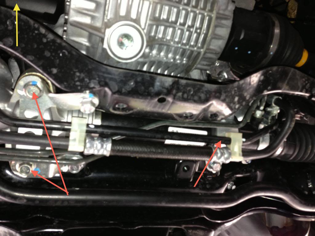
3.) Once the cross member support is removed the steering rack will be exposed as pictured below. Note the location of the 3 bushings denoted by the red arrows.
Steering Rack Bushings Install on a 08+ STi: Note the location of the 3 bushings denoted by the red arrows.
Subaru’s power steering system contains a pump, hydraulic line, and a gearbox (rack). The hydraulic pump is a vane-type pump driven by the engine. It provides pressurized fluid for the system.
Power Steering Systems On Early Subarus Part 2: Subaru’s power steering system contains a pump, hydraulic line, and a gearbox (rack). The hydraulic pump is a vane-type pump driven by the engine. It provides pressurized fluid for the system.
Oil Pump Operation
The pump has two internal valves: a flow control valve and a relief valve. The flow control valve regulates the volume of power steering fluid delivered to the rack. During high engine rpm, the pressure in the pump overcomes the flow control valve spring. The control valve slides back to close off an oil passage to the rack and to open an oil return port to the pump inlet. This reduces the power assist to the rack during high speeds, improving the steering wheel feel and response.
Subaru steering systems utilize a rack and pinion steering mechanism. As the pinion gear rotates, the rack moves left or right. Rack and pinion steering gives the driver precise control over the wheels. The simple, compact design is easy to service.
Steering Systems on early Subarus Part 1: The Subaru SVX used Subaru’s early power steering system.
CGR – VGR Ratios
Two manual steering racks are used in Subaru vehicles: a constant gear ratio (CGR) rack and a variable gear ratio (VGR) rack. The teeth on the CGR rack are equally spaced so the turning effort is equal throughout the turning range. The teeth on the VGR rack are spaced closer together on the ends of the rack than in the middle. The turning effort decreases as the turning angle increases so sharp-radius turns are easier to make.
Several different power steering racks have been installed in Subaru vehicles. The racks used in the L-series, XT, Legacy and SVX vehicles are similar. All have a one-piece gearbox and lack the external air vent distribution tube found on the rack in pre-’85 and carryover vehicles. However, the XT rack differs from the L-series rack in several ways.
The XT rack is made of aluminum and has a different control valve. Different types of hydraulic seals are used in the two racks, and each has its own unique special service tool. The power steering rack in the pre-’85 model year vehicles and the Brat has a two-piece gearbox and an air vent distribution tube. It also has seals, service procedures and special service tools that differ from the other racks.
Rigid Steering Column
Three types of steering columns are used in Subaru vehicles: a rigid steering column, a tilt steering column and the XT and SVX tilt and telescoping steering column. The rigid steering column is found on L-series DL models, the Legacy standard model, and Justy vehicles. The rigid steering shaft does not tilt or pop-up, but is collapsible (a safety feature). The shaft is connected to the gearbox by universal joints.
ABS 5.3 Antilock Brake System for Early Subaru Part 5:
ABS 5.3 Antilock Brake System for Early Subaru Part 5: Beginning in approximately December of 1996, a new antilock braking system called ABS 5.3 was installed on Legacy vehicles equipped with ABS.
Beginning in approximately December of 1996, a new antilock braking system called ABS 5.3 was installed on Legacy vehicles equipped with ABS. This system uses a Bosch hydraulic control unit and a Nippon electronic control unit. ABS 5.3 is a four channel control design which can independently control the front wheels and utilize select low control to control the rear wheels (a system which provides the same fluid pressure control for the two rear wheels if either wheel starts to lock up).
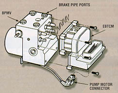
Although similar to other Subaru ABS systems, there have been enhancements to component operation and location. Diagnosis has also improved because of the ability of the 5.3 ABS system to communicate with the Select Monitor. The hydraulic control unit or HCU is located under the hood on the right side of the engine compartment. The size of the HCU has decreased by approximately a third from that of the ABS-2E system, used on previous model year vehicles.
The HCU controls brake fluid flow by utilizing eight solenoid valves. There is an inlet solenoid valve and an outlet solenoid valve for each wheel. Mechanically, the inlet solenoid valve is open during normal braking, and the outlet solenoid valve is closed. The HCU also contains a motor and pump assembly, which operates only while ABS is actively controlling the brake fluid flow–preventing a wheel lock.
ABS 5.3: Beginning in approximately December of 1996, a new antilock braking system called ABS 5.3 was installed on Legacy vehicles equipped with ABS.
Externally the HCU of the ABS 5.3 has a relay box attached. This allows troubleshooting of the valve and motor relay area to be kept separate from the troubleshooting of the solenoid valves and pump motor. There are four modes of operation for the ABS 5.3 system. They are normal, pressure-drop, pressure-hold and pressure-increase. When wheel lockup is sensed, Mode Two, Mode Three and Mode Four may be activated. They are described as follows:
We use cookies on our website to give you the most relevant experience by remembering your preferences and repeat visits. By clicking “Accept”, you consent to the use of ALL the cookies.
This website uses cookies to improve your experience while you navigate through the website. Out of these, the cookies that are categorized as necessary are stored on your browser as they are essential for the working of basic functionalities of the website. We also use third-party cookies that help us analyze and understand how you use this website. These cookies will be stored in your browser only with your consent. You also have the option to opt-out of these cookies. But opting out of some of these cookies may affect your browsing experience.
Necessary cookies are absolutely essential for the website to function properly. These cookies ensure basic functionalities and security features of the website, anonymously.
Cookie
Duration
Description
cookielawinfo-checkbox-analytics
11 months
This cookie is set by GDPR Cookie Consent plugin. The cookie is used to store the user consent for the cookies in the category "Analytics".
cookielawinfo-checkbox-functional
11 months
The cookie is set by GDPR cookie consent to record the user consent for the cookies in the category "Functional".
cookielawinfo-checkbox-necessary
11 months
This cookie is set by GDPR Cookie Consent plugin. The cookies is used to store the user consent for the cookies in the category "Necessary".
cookielawinfo-checkbox-others
11 months
This cookie is set by GDPR Cookie Consent plugin. The cookie is used to store the user consent for the cookies in the category "Other.
cookielawinfo-checkbox-performance
11 months
This cookie is set by GDPR Cookie Consent plugin. The cookie is used to store the user consent for the cookies in the category "Performance".
viewed_cookie_policy
11 months
The cookie is set by the GDPR Cookie Consent plugin and is used to store whether or not user has consented to the use of cookies. It does not store any personal data.
Functional cookies help to perform certain functionalities like sharing the content of the website on social media platforms, collect feedbacks, and other third-party features.
Performance cookies are used to understand and analyze the key performance indexes of the website which helps in delivering a better user experience for the visitors.
Analytical cookies are used to understand how visitors interact with the website. These cookies help provide information on metrics the number of visitors, bounce rate, traffic source, etc.
Advertisement cookies are used to provide visitors with relevant ads and marketing campaigns. These cookies track visitors across websites and collect information to provide customized ads.